
Rolling type six-shuttle plastic cylindrical knitting machine

A rolling type braiding machine technology, applied in the field of braiding machines, can solve the problems of lack of tacit understanding of the body, poor controllability, poor practical performance, etc., and achieve the effect of improving the assembling effect, high precision performance, and improving stability performance.

Pending Publication Date: 2020-09-11
江苏润亿通用装备有限公司
View PDF0 Cites 0 Cited by
  • Summary
  • Abstract
  • Description
  • Claims
  • Application Information

AI Technical Summary

Problems solved by technology

[0004] The purpose of the present invention is to provide a rolling six-shuttle plastic cylinder knitting machine to solve the problem that the existing knitting machine proposed in the background technology is very empty due to its frame body, which may cause it to be used. The control performance is poor. At the same time, it is impossible to use the frame body to assemble some peripherals, such as fans for drying and purification, and the knitting cable winding on the side of the roll-shaped object cannot be adjusted in height by itself, causing it to cooperate with the body when used. It doesn't look tacit enough, and the practical performance is poor

Method used


Image

  • Rolling type six-shuttle plastic cylindrical knitting machine
  • Rolling type six-shuttle plastic cylindrical knitting machine
  • Rolling type six-shuttle plastic cylindrical knitting machine

Examples


Embodiment Construction

[0026] The following will clearly and completely describe the technical solutions in the embodiments of the present invention with reference to the accompanying drawings in the embodiments of the present invention. Obviously, the described embodiments are only some, not all, embodiments of the present invention.

[0027] In the description of the present invention, unless otherwise stated, the meaning of "plurality" is two or more; the terms "upper", "lower", "left", "right", "inner", "outer" , "front end", "rear end", "head", "tail", etc. indicate the orientation or positional relationship based on the orientation or positional relationship shown in the drawings, and are only for the convenience of describing the present invention and simplifying the description, rather than Nothing indicating or implying that a referenced device or element must have a particular orientation, be constructed, and operate in a particular orientation should therefore not be construed as limiting ...


PUM


Abstract

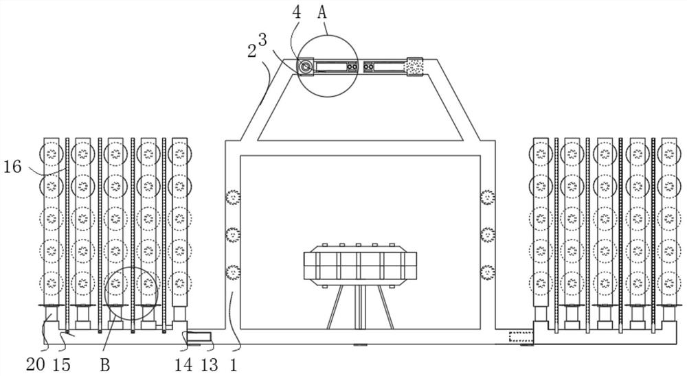
The invention relates to a rolling type six-shuttle plastic cylindrical knitting machine. The rolling type six-shuttle plastic cylindrical knitting machine comprises a main rack and a blocking slot, wherein an upper rack is mounted at the top end of the main rack; a carrying hanging mechanism is mounted inside the top end of the upper rack; an inner slot hole is formed in the inner side wall of the top end of the main rack; a padding mechanism is mounted at the inner end of the inner slot hole; the blocking slot is formed in the bottom side end of the main rack; a buckle is mounted inside theblocking slot; the side end of the buckle is fixedly provided with a pin base ruler; and the side wall of a pin base is fixedly provided with a ruler. The rolling type six-shuttle plastic cylindricalknitting machine disclosed by the invention has the beneficial effects that: a lower rod and an upper rod can move to regulate a distance between the lower rod and the upper rod, so that a height position of the upper rod can be conveniently regulated, and control use can be performed better; and moreover, height positions of different lower rods are changed to sort and regulate height of the lower rods better, and height positions of textile threads on the end parts of the lower rods are controlled, so that the knitting machine conveniently works better.

Description

technical field [0001] The invention relates to the technical field of knitting machines, in particular to a rolling six-shuttle plastic cylinder knitting machine. Background technique [0002] The types of raw materials applicable to the knitting machine are: nylon multifilament (thread), polypropylene filament (thread), polypropylene, polyester, nylon, PP, low elastic, high elastic, cotton yarn (thread), pearl light, leather, mixed, etc. The high-speed jogging knitting machine has a complete set of N-color automatic switching devices, and is driven by a computer-controlled motor to automatically switch between yarn feeders, making multi-color pattern knitting simple and easy. Its high-performance knitting action can easily complete the high-quality pattern knitting that can only be done on large-scale computer knitting machines, and it is the miniaturization of high-end computer knitting. [0003] The existing knitting machine has the problem of poor controllability due t...

Claims


Application Information

Patent Timeline
IPC IPC(8): D04B9/00D04B15/40D04B35/32
CPCD04B9/00D04B15/40D04B35/32
Inventor 胡岩岩
Owner 江苏润亿通用装备有限公司
Learn More