Melt-blown cloth and preparing system and preparing process thereof

A preparation system and technology of melt-blown cloth, applied in the direction of non-woven fabric, rayon manufacturing, spinneret assembly, etc., can solve the problems of inability to control the width of melt-blown cloth and edge cutting, etc., and achieve density increase and decrease Effect of receiving distance, high loft and air permeability

Active Publication Date: 2020-09-11
温州珍康医疗用品有限公司
View PDF10 Cites 12 Cited by
  • Summary
  • Abstract
  • Description
  • Claims
  • Application Information

AI Technical Summary

Problems solved by technology

However, the device cannot control the width of the produced melt-blown cloth, and cannot cut the edge

Method used


Image

  • Melt-blown cloth and preparing system and preparing process thereof
  • Melt-blown cloth and preparing system and preparing process thereof
  • Melt-blown cloth and preparing system and preparing process thereof

Examples


specific Embodiment approach 1

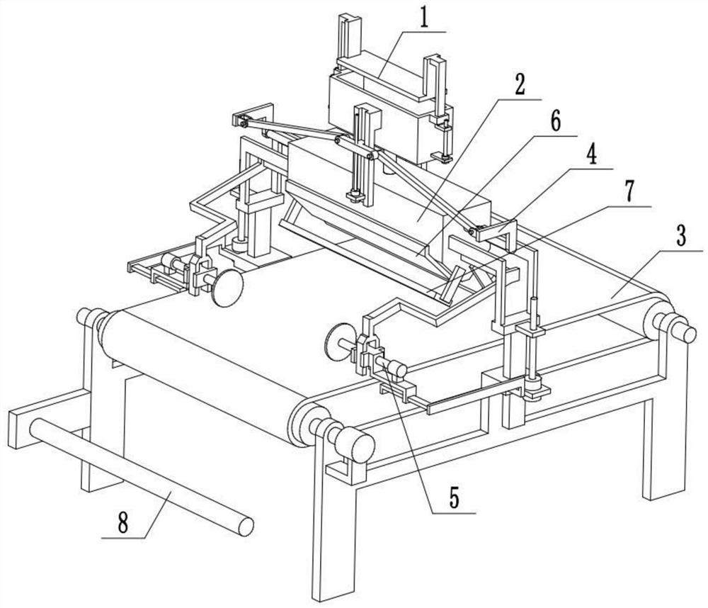
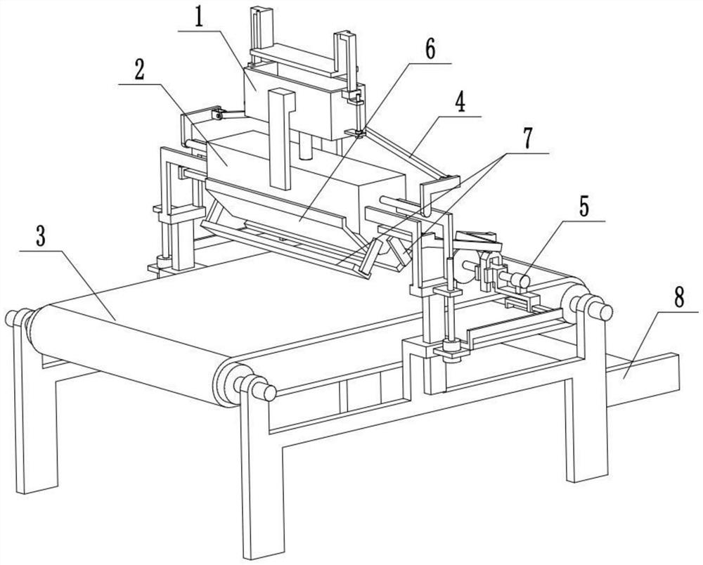
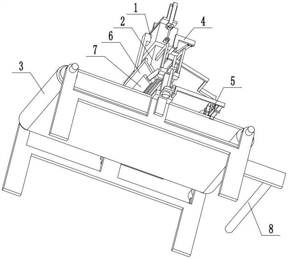
[0033] Combine below Figure 1-9Describe this embodiment, a melt-blown cloth preparation system, including a blanking device 1, a nozzle assembly 2, a receiving device 3, a width adjusting device 4, an edge trimming device 5, a high-temperature airflow generator 6, a cooling airflow generator 7 and a receiving device The cloth roller 8, the described unloading device 1 is fixedly connected to the nozzle assembly 2, the nozzle assembly 2 is connected to the receiving device 3, and the two width adjustment devices 4 are symmetrically arranged at the two ends of the nozzle assembly 2, and the two edge trimmers The device 5 is symmetrically and flexibly connected to both ends of the receiving device 3, and the two width adjusting devices 4 are respectively flexibly connected to the two trimming devices 5, and the two high-temperature airflow generators 6 are symmetrically arranged at both ends of the nozzle assembly 2, and the nozzle assembly 2 Two cooling airflow generators 7 are...

specific Embodiment approach 2

[0035] Combine below Figure 1-9 To illustrate this embodiment, the blanking device 1 includes a melt box 1-1, a blanking pipe 1-2, a fixed plate 1-3, a vertical chute 1-4, a first motor 1-5, a first screw 1-6, L-shaped rod 1-7, sliding sleeve 1-8 and U-shaped pressing plate 1-9; the lower end of the melting material box 1-1 is fixedly connected and communicated with the feeding pipe 1-2, and the feeding pipe 1-2 is connected with the The nozzle assembly 2 is connected, and the two ends of the melt box 1-1 are respectively fixedly connected to a fixed plate 1-3, and the two fixed plates 1-3 are fixedly connected to the nozzle assembly 2, and the fixed plate 1-3 at the left end is provided with The vertical chute 1-4, the two first motors 1-5 are respectively fixedly connected to the two ends of the melting tank 1-1 through the motor frame, and the two first motors 1-5 are respectively connected to a first motor 1-5 through a coupling. The screw rod 1-6, the lower ends of the ...

specific Embodiment approach 3

[0037] Combine below Figure 1-9 To illustrate this embodiment, the nozzle assembly 2 includes a melt blown die head 2-1, a side frame 2-2, a telescopic frame 2-3 and a spinneret hole 2-4; the feeding pipe 1-2 is fixedly connected and connected On the upper end of the melt-blown die head 2-1, the two fixing plates 1-3 are fixedly connected to the melt-blown die head 2-1, and the two ends of the melt-blown die head 2-1 are respectively fixedly connected to a side frame 2- 2. A telescopic frame 2-3 is fixedly connected to the two side frames 2-2, and the two telescopic frames 2-3 are connected with the receiving device 3, and the lower end of the meltblown die head 2-1 is provided with a spinneret hole 2-4, two high-temperature airflow generators 6 are symmetrically arranged at the lower ends of the melt-blown die head 2-1, and two cooling airflow generators 7 are symmetrically arranged at the lower end of the melt-blown die head 2-1; the cooling airflow occurs The device 7 is ...


PUM


Abstract

The invention relates to melt-blown cloth and a preparing system and a preparing process thereof. The melt-blown cloth comprises the following components including, by weight, 75 parts of polypropylene resin, 35 parts of polyethylene terephthalate, 22 parts of titanium dioxide, 3 parts of a dispersing agent, 5 parts of a stabilizing agent and 3 parts of an auxiliary agent. The process comprises the following steps of 1, putting a raw material solution into a discharging device, and pressing the solution into a spray head assembly after the discharging device is started; 2, under the drafting action of two high-temperature airflow generators, forming superfine fibers by using the raw material solution sprayed out of the spray head assembly; 3, conducting bonding on the sprayed superfine fibers under the action of self-bonding, and forming the melt-blown cloth on a receiving device through cooling of two high-temperature airflow generators; 4, enabling the running receiving device to drive the melt-blown cloth to be conveyed leftwards and wound on a cloth winding roller; and 5, cutting the two ends of the melt-blown cloth by two edge cutting devices.

Description

technical field [0001] The invention relates to the technical field of melt-blown cloth production, more specifically a melt-blown cloth and its preparation system and preparation process. Background technique [0002] The patent number is CN201410524317.5, a method for preparing fluffy melt-blown cloth, the invention relates to a method for preparing fluffy melt-blown cloth; raw materials are heated, melted and extruded through a screw extruder, filtered through a filter, and then transported through a pipeline The melt is measured by the metering pump, and then sent to the die head, and fine fibers are formed under the drafting action of high-speed hot air. Under the action of negative pressure, the fiber is laid on the web forming table to form a non-woven fabric; it solves the problems of hard hand feeling of the cloth surface, poor fluffy performance of the fiber, and thin cloth surface thickness; it is fluffy, tough and soft to the touch. However, this device cannot c...

Claims


Application Information

Patent Timeline
IPC IPC(8): D04H1/56D04H1/541D06H7/06D01D4/02D01F8/06D01F8/14D01F1/10
CPCD01D4/02D01F1/10D01F8/06D01F8/14D04H1/541D04H1/56D06H7/06
Inventor 曹聪
Owner 温州珍康医疗用品有限公司
Why Eureka
Try Eureka