Optical adjusting frame capable of slowing down drifting

A technology of optical adjustment frame and screw rod, applied in the field of optical adjustment frame, can solve the problems of hindering the one-way rigid bonding of screw teeth, high price, processing of wear parts, etc., and achieve the effect of improving the piston effect and improving the position stability.

Pending Publication Date: 2020-09-11
SHANGHAI INST OF OPTICS & FINE MECHANICS CHINESE ACAD OF SCI
View PDF0 Cites 0 Cited by
  • Summary
  • Abstract
  • Description
  • Claims
  • Application Information

AI Technical Summary

Problems solved by technology

like image 3 Shown is a schematic diagram of the screw teeth engagement when the nut in the commonly used optical adjustment mount is unidirectionally tensioned. Continue to screw in the screw 3 and finally lean against the front plate 1. Under the unidirectional tension of the spring 4, the screw 3 One-way fit between the screw teeth of the nut 6, that is, the screw teeth 8 on the nut 6 are attached to the screw teeth 9 on the screw rod 3, because the pressure side is filled with too much grease 11, hindering the one-way rigidity of the screw teeth Fitting, producing the piston effect of flexible contact, this phenomenon makes the relative position of the screw and the nut susceptible to small changes due to environmental changes (such as temperature changes and vibration shocks), that is, the drift phenomenon, which will directly reflect On the optical adjustment mount, for the optical parts used in the high-power laser optical system, any small position change will also have a great impact on the optical system
[0004] Some manufacturers choose not to add lubricants, but choose wear-resistant materials for precision machining, control the clearance of the thread fit and the roughness of the thread surface, so that the fine-tuning structure of the thread can achieve rigid contact to improve the drift of the optical adjustment mount, but this Structural work will also cause wear and tear for a certain period of time, and the requirements for materials and processing of parts are relatively strict, and the price is relatively expensive

Method used


Image

  • Optical adjusting frame capable of slowing down drifting
  • Optical adjusting frame capable of slowing down drifting
  • Optical adjusting frame capable of slowing down drifting

Examples


Embodiment Construction

[0021] Below in conjunction with accompanying drawing and specific embodiment the present invention is described in further detail:

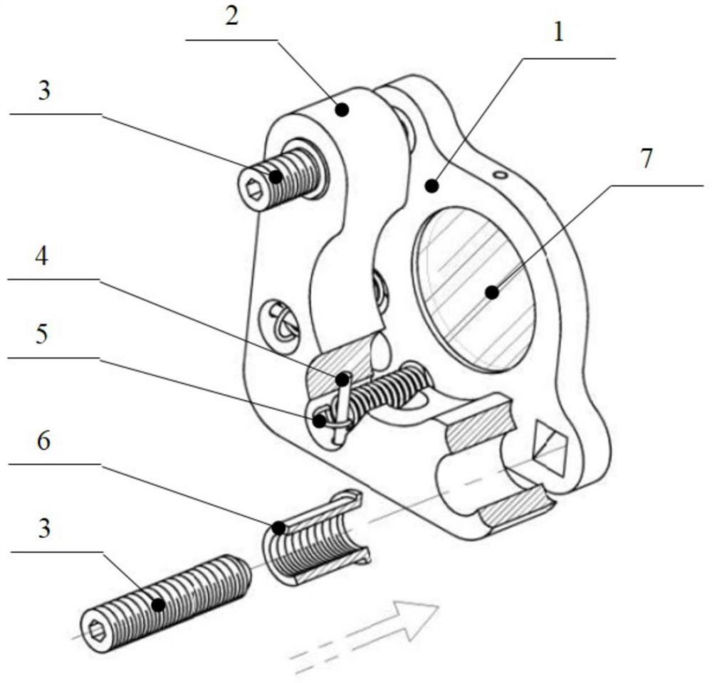
[0022] Such as Figure 4 It is an exploded view of an optical adjustment mount that can slow down drift, including 1 front plate 1, 1 base plate 2, 2 screw rods 12, 2 nuts 13, 2 springs 4, 4 pins and 1 pivot ball 14;

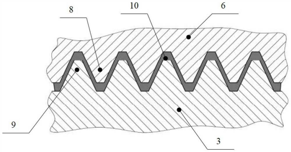
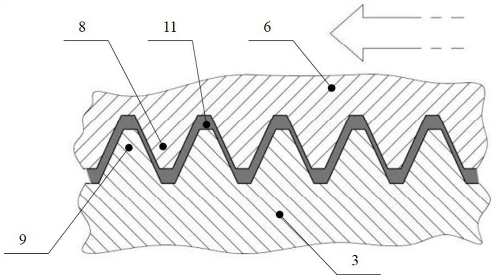
[0023] Such as Figure 5 It is an enlarged view of the specific structure and shape of the screw rod and the nut in the current invention. The cylindrical surface of the screw rod 12 is an external thread 15, which is matched with the internal thread 20 of the nut 13, and the left end surface has an inner hexagonal groove 16, so that it can be inserted into the corresponding Use a hexagonal wrench to adjust the position of the screw, and the end surface on the right side is a spherical tip 17, which realizes point contact with the front plate 1;

[0024] The left side of the nut 13 is a cylindrical surface 18, which is used for...


PUM


Abstract

An optical adjusting frame capable of slowing down drifting comprises a front plate, a base plate, a lead screw and a nut. The frame is characterized in that the screw rod is cylindrical, external threads are arranged on the surface of the screw rod, one end of the screw rod is an inner hexagonal groove end, and the other end of the screw rod is a spherical tip. One end of the nut is a cylindricalsurface, the other end of the nut is provided with a step, an internal thread is arranged in the nut and matched with an external thread of the lead screw, the cylindrical surface is provided with axial grooves which are evenly distributed in the circumferential direction, and the axial grooves penetrate through the whole length of the internal thread. The nut is fixed to the base plate, the leadscrew is screwed into the nut in a spiral fit mode, and the spherical tip end of the lead screw abuts against the front plate. The invention aims to improve the non-rigid contact piston effect causedby filling excessive lubricating grease on the pressed side of the screw-thread fit screw tooth surface, thereby improving the position stability of the optical adjustment frame. The frame is simplein structure, low in nut machining requirement, gapless in transmission, good in long-term stability and suitable for precise micro-adjustment of the angle and the position of an optical element.

Description

technical field [0001] The invention relates to the technical field of optical adjustment mounts, in particular to an optical adjustment mount capable of slowing down drift, which is mainly used for precise micro-adjustment of the angle and displacement of optical components. Background technique [0002] figure 1 Shown is a schematic diagram of an existing optical adjustment mount, which is mainly composed of a front plate 1, a base plate 2, two adjustment screw rods 3, two springs 4, four pins 5 and two nuts 6, It is mainly used to finely adjust the position of the optical part 7 installed on the front plate 1, wherein the nut 6 is first fixed together with the base plate 2 through the outer cylindrical surface, and the screw rod 2 is screwed into the nut 6 through screw fit until the screw rod The spherical tip on 3 leans against the front plate 1, and the spring 4 is opened by the pins 5 respectively inserted on the front plate 1 and the base plate 2. Under the tension ...

Claims


Application Information

Patent Timeline
Patent Type & Authority Applications(China)
IPC IPC(8): G02B7/00
CPCG02B7/00G02B7/004G02B7/003F16D1/05
Inventor 张朝朱健强汤更秀杜李峰刘志刚
Owner SHANGHAI INST OF OPTICS & FINE MECHANICS CHINESE ACAD OF SCI
Why Eureka
Try Eureka