Galvanometer parameter adjusting method, device and equipment and readable storage medium
A parameter adjustment and parameter technology, applied in image data processing, optics, instruments, etc., can solve the problems of low working performance of galvanometer and inappropriate setting of galvanometer parameters, and achieve the effect of ensuring performance and ensuring a reasonable degree
- Summary
- Abstract
- Description
- Claims
- Application Information
AI Technical Summary
Problems solved by technology
Method used
Image

Examples
Embodiment Construction
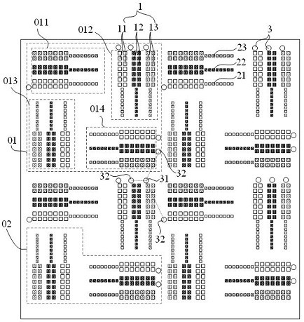
[0058] Such as figure 1 as shown, figure 1 A schematic diagram of the vibration image of the galvanometer. It should be noted that the vibrating image referred to in this application is the image generated by using the three light sources of red, green and blue to emit parallel light beams to mix and enter the vibrating mirror and output to the photosensitive chip from the vibrating mirror. Commonly used test images, which will not be described in detail.
[0059] The vibrating image contains multiple basic vibrating images 01 , and the content of the entire vibrating image is the repetition of the multiple basic vibrating images 01 . The basic vibration image 01 includes four groups of thick vibration lines and thin vibration lines, namely vibration line 1 011, vibration line 2 012, vibration line 3 013 and vibration line 4 014.
[0060] Among them, 1011 kinds of vibrating lines include red vibrating thick line 11, red vibrating thin line 21, green vibrating thick line 12,...
PUM
 Abstract
Description
Claims
Application Information
PatSnap Eureka turns technology decisions into work you can execute. Powered by our Innovation Knowledge Graph, it runs expert workflows across engineering, life sciences, materials and intellectual property. Get your review-ready output in minutes.


