Motor

A technology of motor shaft and motor body, applied in the direction of electrical components, electromechanical devices, electric components, etc., can solve the problems of easy attenuation of resistance, short service life, easy attenuation of resistance and service life, and achieve long-term resistance maintenance, long service life, The effect of increasing the detent moment

Pending Publication Date: 2020-09-11
深圳市德立威汽车部件有限公司
View PDF0 Cites 0 Cited by
  • Summary
  • Abstract
  • Description
  • Claims
  • Application Information

AI Technical Summary

Problems solved by technology

[0005] 1. Without a damper, the positioning torque is only formed by the magnetic pull of the motor's own rotor and stator. The advantages of this structure are: the length of the motor assembly is short and the cost is low. The disadvantage is: it cannot provide a large positioning torque;
[0006] 2. Install a damper at the output end of the gearbox, and provide additional positioning torque through the damper, so that the motor has a greater positioning torque. The advantages of this structure are: large positioning torque, simple motor structure, and shorter length Short; the disadvantages are: high cost of the damper, easy to wear, easy to attenuate resistance, short service life,
[0007] Based on the above two structures of the motor, it can be known that the existing motor either has the problem of insufficient positioning torque, or has the problems of high cost, easy attenuation of resistance and short service life. Therefore, it is necessary to improve the existing motor. In order to provide a new motor, the electrode of the reduction box can have the characteristics of low cost, long service life and long-term resistance while having a high positioning torque

Method used


Image

  • Motor
  • Motor
  • Motor

Examples


Embodiment Construction

[0034] In order to further illustrate the technical means adopted by the present invention and its effects, the following describes in detail in conjunction with preferred embodiments of the present invention and accompanying drawings.

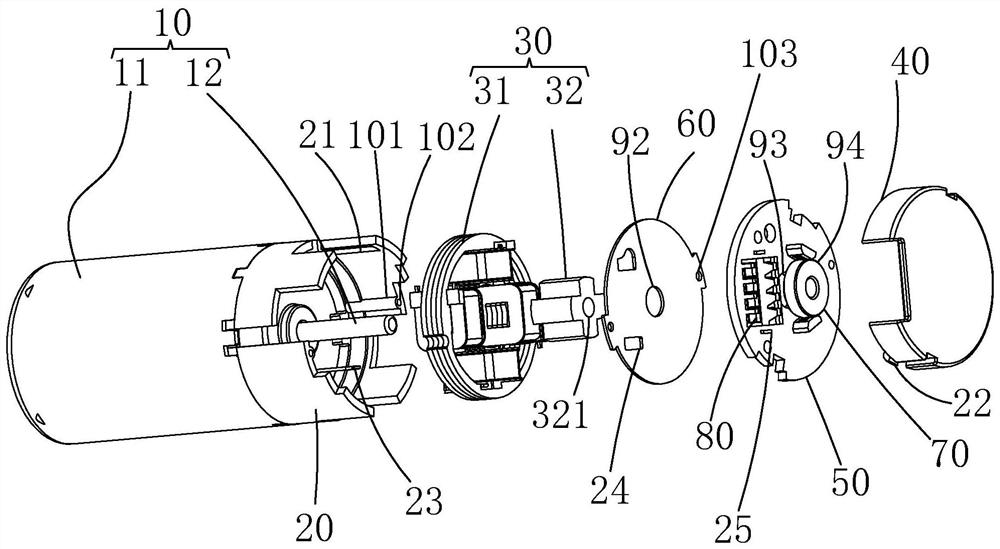
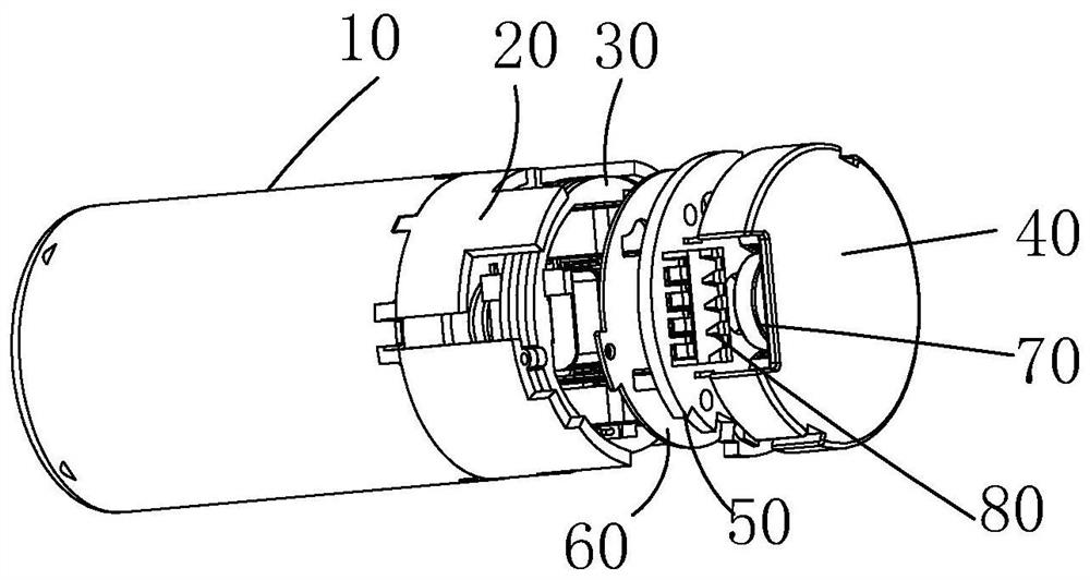
[0035] see Figure 1 to Figure 4 , the present invention provides a motor, including: a motor body 10, a rubber cover 20 and an electromagnetic damper 30;

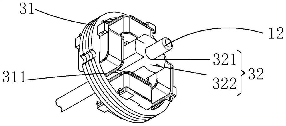
[0036] The motor body 10 includes: a casing 11 and a motor shaft 12 protruding from one end of the casing 11;

[0037] The rubber cover 20 is mounted on one end of the casing 11;

[0038] The electromagnetic damper 30 is installed in the rubber cover 20 and connected with the motor shaft 12;

[0039] The electromagnetic damper 30 can follow the rotation of the motor shaft 12 when the power is off, and can apply resistance to the motor shaft 12 opposite to the rotation direction of the motor shaft 12 when the power is on.

[0040] Wherein, when the electromagnetic damper 30 is energized,...


PUM


Abstract

The invention provides a motor. The motor comprises a motor body, a rubber cover and an electromagnetic damper. The motor body comprises a machine shell and a motor shaft extending out of one end of the machine shell. The rubber cover is installed at one end of the machine shell. The electromagnetic damper is arranged in the rubber cover and is connected with the motor shaft. The electromagnetic damper can rotate along with the motor shaft when powered off, resistance opposite to the rotating direction of the motor shaft can be applied to the motor shaft when powered on, resistance can be provided through the electromagnetic damper to increase positioning torque, the service life is long, and the resistance can be kept for a long time.

Description

technical field [0001] The invention relates to the technical field of motors, in particular to a motor. Background technique [0002] Motor refers to an electromagnetic device that realizes the conversion or transmission of electric energy according to the law of electromagnetic induction. Its main function is to generate driving torque as a power source for electrical appliances or various machinery. According to the type of working power supply, it can be divided into DC motor and AC motor. DC motors can be divided into brushless DC motors and brushed DC motors according to their structure and working principle. [0003] The reduction box is an independent component composed of a gear transmission enclosed in a metal or non-metal shell. It is often used in the reduction transmission between the driving part and the driven part, and at the same time achieves the effect of increasing the torque. With its ingenious and compact structure inside, the gearbox can realize high...

Claims


Application Information

Patent Timeline
Patent Type & Authority Applications(China)
IPC IPC(8): H02K7/10H02K5/04H02K11/30H02K11/01H02K11/215
CPCH02K5/04H02K7/10H02K11/01H02K11/215H02K11/30
Inventor 唐宪
Owner 深圳市德立威汽车部件有限公司
Why Eureka
Try Eureka