
Piston for printhead of 3D printer and printhead for 3D printer

A technology of 3D printers and print heads, which is applied in the direction of printing, process efficiency improvement, inking device, etc. It can solve the problems of inaccurate printing process, troublesome working steps, retention of gas inclusions, etc., and achieve improved repeatability and improved discharge Effect

Active Publication Date: 2020-09-11
ROBERT BOSCH GMBH
View PDF4 Cites 2 Cited by
  • Summary
  • Abstract
  • Description
  • Claims
  • Application Information

AI Technical Summary

Problems solved by technology

This piston shape has the disadvantage that a so-called "dead zone" may form under the surface or in the middle of the surface
[0009] Furthermore, gas inclusions remain on the surface or underside of the punch during start-up of the printing head, and complex work steps are required in order to reduce or remove the gas inclusions
[0010] If gaseous inclusions are in the extrusion chamber when the 3D printer is running, these gaseous inclusions act as a compressible medium and dampen the pressure shocks of the punch, so that the printing process may be imprecise or even stalled

Method used


Image

  • Piston for printhead of 3D printer and printhead for 3D printer
  • Piston for printhead of 3D printer and printhead for 3D printer
  • Piston for printhead of 3D printer and printhead for 3D printer

Examples


Embodiment Construction

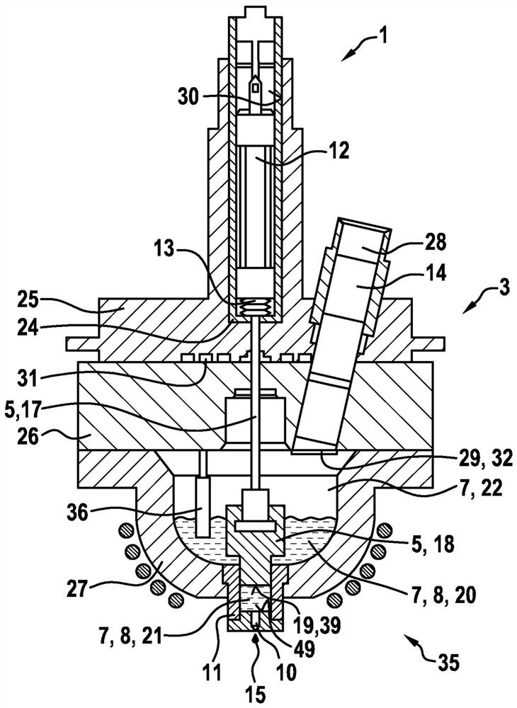
[0034] figure 1 An embodiment of a print head 1 for a 3D printer according to the invention is shown.

[0035] The print head 1 comprises a housing 3 , means 28 for supplying metal 14 in the solid phase, reservoirs 7 , 27 , nozzle means 2 with discharge openings 10 and a piston 5 . Furthermore, the print head comprises actuator means 12 for moving the piston 5 . The reservoirs 7 , 27 have a melting zone 20 and an extrusion chamber 21 for the liquid phase 8 of the metal 14 , wherein the melting zone 20 adjoins an inert gas atmosphere 22 and is connected to the extrusion chamber 21 in such a way that the piston 5 The movement of can cause the liquid phase 8 of the metal 14 to flow out through the discharge opening 10 . Liquid phase 8 of metal 14 or liquid metal 8 is also referred to as melt 8 and inert gas atmosphere 22 is formed by introducing inert gas 22 into reservoirs 7 , 27 . The inert gas atmosphere 22 is preferably introduced into the reservoir 7 , 27 via the cold reg...


PUM


Abstract

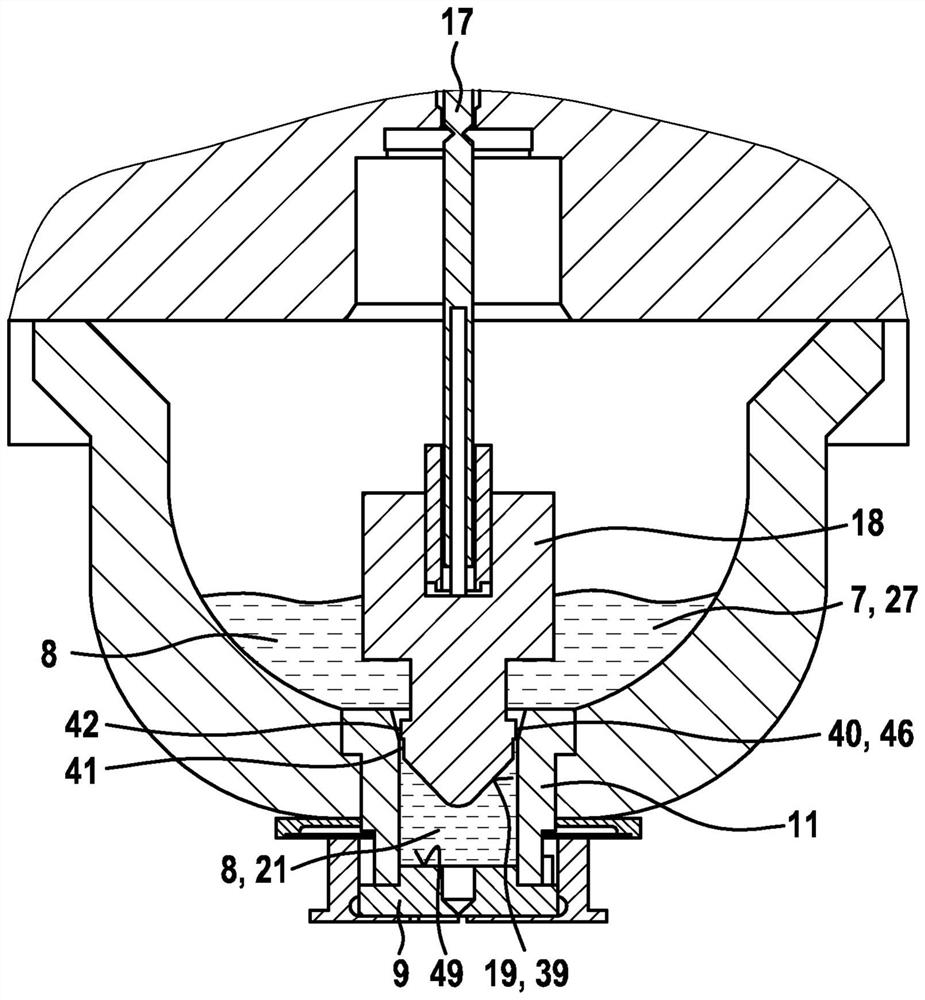
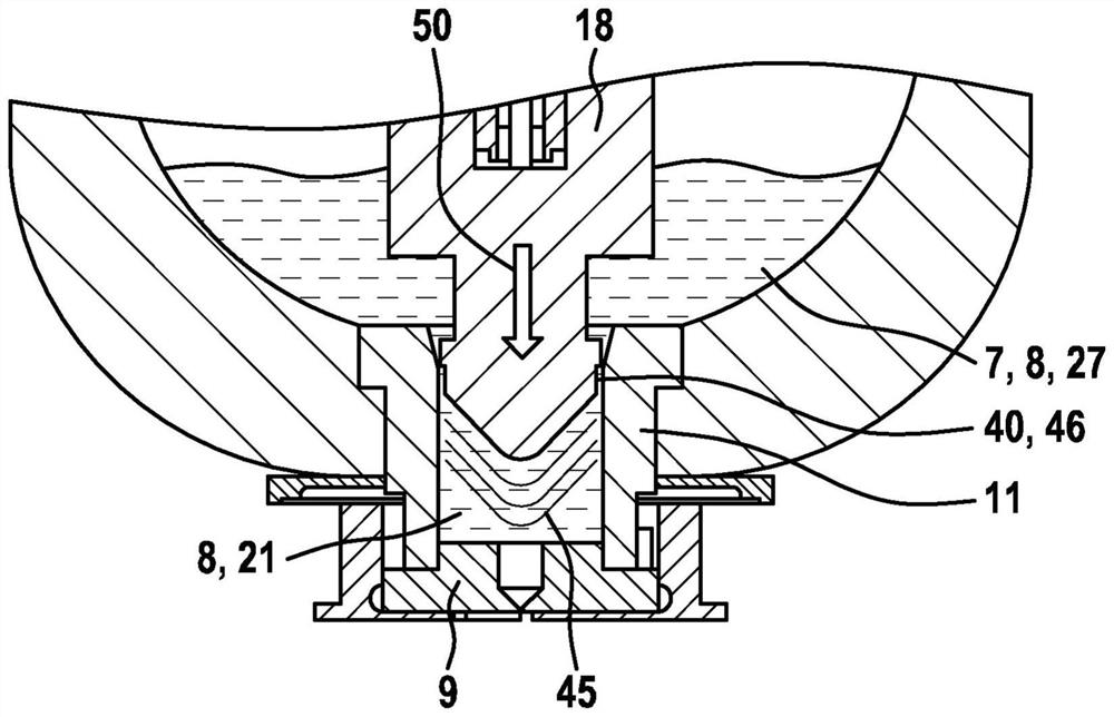
The invention relates to a piston (5) for a printhead (1) of a 3D printer, particularly a metal printer, comprising a piston rod (17) and a ram (18), the ram (18) having a discharge side (19) that hasa convex or tapering surface (39). The invention also relates to a printhead (1) for a 3D printer, particularly a metal printer, comprising a housing (3), a device (28) for supplying a metal (14), areservoir (7, 27) for a liquid phase (8) of the metal (14), a nozzle device (2) comprising a guide sleeve (11) and a nozzle plate (9), and a piston (5) according to one of the preceding claims, the ram (18), the guide sleeve (11) and the nozzle plate (9) forming a displacement chamber (21), and the ram (18) and the guide sleeve (11) forming at least one area (40) for conducting the liquid phase (8) between the reservoir (27) and the displacement chamber (21).

Description

technical field [0001] The invention relates to a piston for a print head of a 3D printer and the 3D printer. Background technique [0002] 3D printers for thermoplastic materials obtain the solid phase of the material as starting material, from which a liquid phase is generated and selectively brought to the regions belonging to the object to be produced. Such 3D printers include a print head into which starting material is melted. Furthermore, means are provided for producing a relative movement between the print head and the working surface on which the object is to be produced. In this case, only the printing head or only the working surface can be moved, or both the printing head and the working surface can also be moved. [0003] The printhead has a first operating state in which liquid material is expelled from the printhead and a second operating state in which no liquid material is expelled from the printhead. For example, the second operating state is assumed if...

Claims


Application Information

Patent Timeline
IPC IPC(8): B22F3/105B22F3/115B33Y30/00
CPCB22F3/115B33Y30/00B41J2202/05B41J2202/04B41J2/14201Y02P10/25B22F10/22B22F12/38B22F12/13B22F12/53B22F12/50B22D23/003
Inventor E·迈尔V·弗里德里希B·施魏策尔B·朔伊费勒
Owner ROBERT BOSCH GMBH
Learn More