Pneumatic tire

A technology for tires and treads, applied in tire parts, tire treads/tread patterns, vehicle components, etc., can solve problems such as poor results, difficult winter tire performance improvement, not forgetting dry ground, etc., to achieve optimal performance, Good grip level, effect of good grip characteristics

Active Publication Date: 2020-09-11
OCIETE DE TECH MICHELIN
View PDF8 Cites 0 Cited by
  • Summary
  • Abstract
  • Description
  • Claims
  • Application Information

AI Technical Summary

Problems solved by technology

However, manufacturers are always looking for performance improvements, especially for winter tires where conditions are particularly difficult, especially because very variable driving conditions such as rain, snow, ice are taken into account and cannot forget about drying the ground
Taking these broad conditions into account is especially tricky, because solutions that work well under some conditions can sometimes lead to worse results under others

Method used


Image

  • Pneumatic tire
  • Pneumatic tire
  • Pneumatic tire

Examples


Embodiment Construction

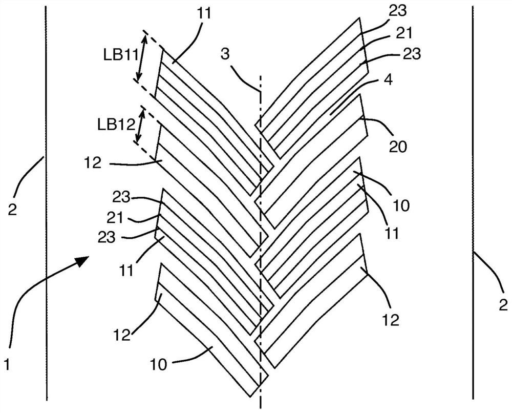
[0032] figure 2 is a schematic diagram showing a first embodiment of a part of the tread 1 of a tire. The tread has two edges 2, a central axis 3 and a plurality of blocks 10 distributed radially over the tread. The blocks 10 are advantageously arranged with a certain inclination or angle of inclination relative to the axis 3 (for example an inclination of between 30° and 60°, and more preferably an inclination of 45°). Hereinafter, this inclination is referred to as the inclination direction of the block.

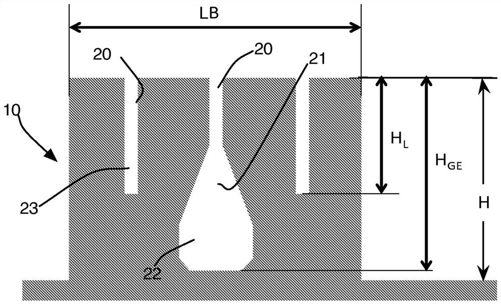
[0033] In this embodiment, the blocks 10 start at a slightly offset position relative to the edge 2 of the tread. These blocks 10 then continue to extend towards the central axis 3 . The plurality of blocks 10 includes at least two adjacent blocks 11 and 12 . The block 11 has a block width LB11, and the block 12 has a block width LB12. These blocks are each provided with at least one sipe 20, 21, 23 extending along the length of the block.

[0034] From figure 2 A...


PUM


Abstract

Pneumatic tire comprising a tread (1) provided with two edges (2), a center (3) and a plurality of tread bars (10) distributed in a circumferential direction, each tread bar (10) extending in an oblique direction from one of the edges (2) towards the center (3) of said tread (1), the plurality of tread bars (10) comprising at least two adjacent tread bars (11, 12), each of said adjacent tread bars(11, 12) having at least one incision (20, 21, 23) extending along the length of the tread bar, wherein widths (LB11, LB12) of said adjacent tread bars (11, 12) and the number of incisions in said adjacent tread bars (11, 12) are different.

Description

technical field [0001] The invention relates to a tire having a tread provided with two edges, a center and a plurality of blocks (blocks) distributed in circumferential direction, each block extending from said edge One of the blocks extends toward the center of the tread in an oblique direction, the plurality of blocks includes at least two adjacent blocks, each of the two adjacent blocks has a at least one sipe extending the length of the block. Background technique [0002] Document FR2998511 describes a tread for snow tires having a plurality of blocks separated by grooves. The blocks are provided with sipes which are divided into a plurality of parts starting from a certain depth, and these sipes are called composite sipes. As seen in cross-section, each compound sipe has a linear first portion extending radially from the tread surface of the tread and continues the first portion and has at least two branches each of which includes The second part of the end. The t...

Claims


Application Information

Patent Timeline
Patent Type & Authority Applications(China)
IPC IPC(8): B60C11/03B60C11/12
CPCB60C11/0304B60C11/0302B60C2011/1209B60C11/0323B60C2011/1268B60C2011/1295
Inventor D·布卢安Q·博纳东M·卡夫罗
Owner OCIETE DE TECH MICHELIN
Why Eureka
Try Eureka