Clamp device used in cooperation with endoscope and clamping part of clamp device

A technology of endoscope and clamping part, which is applied in the field of clip device and its clamping part, which can solve the problems of many parts, complex assembly structure, unfavorable clip opening and closing repeatedly, etc., and achieve high stability and structural stability Good results

Active Publication Date: 2020-09-15
ANREI MEDICAL HZ
View PDF15 Cites 0 Cited by
  • Summary
  • Abstract
  • Description
  • Claims
  • Application Information

AI Technical Summary

Problems solved by technology

However, the inventor believes that in this structure, there are many components, the assembly structure is complicated, and the process steps are many, and the movable positioning between the clip and the push-pull seat is not reliable enough, and the operation operation is not convenient and reliable enough, which still needs further improvement to reduce the manufacturing cost. cost
The Chinese patent document whose publication number is CN110464410A has been improved based on the previous patent. It discloses a practical clip device and its clamping part for endoscopes. The front end of the push-pull seat is provided with a connecting part, and the front part of the connecting part is Radial pins protrude to the left and right sides respectively, and the tails of the two clips are respectively set on the two radial pins through holes so as to realize the flexible connection between the clip and the push-pull seat. This scheme has fewer parts , The structure is simple and the assembly is simple. During the separation process, the tail of the clip springs open symmetrically without debris remaining, but the movable positioning between the clip and the push-pull seat is still not reliable enough. During the process of opening and closing or rotating, the tail of the clip has a certain The probability of popping off and getting stuck on the stop part is not conducive to the repeated opening and closing of the clip

Method used


Image

  • Clamp device used in cooperation with endoscope and clamping part of clamp device
  • Clamp device used in cooperation with endoscope and clamping part of clamp device
  • Clamp device used in cooperation with endoscope and clamping part of clamp device

Examples


Embodiment 1

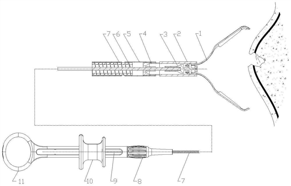
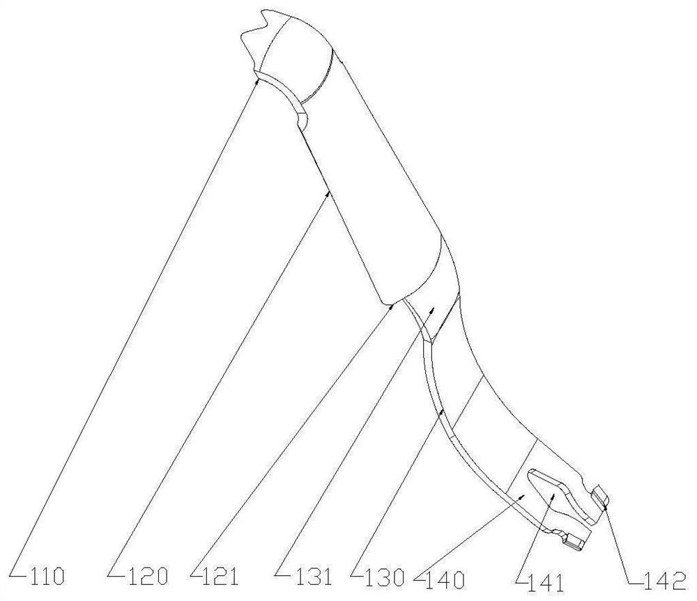
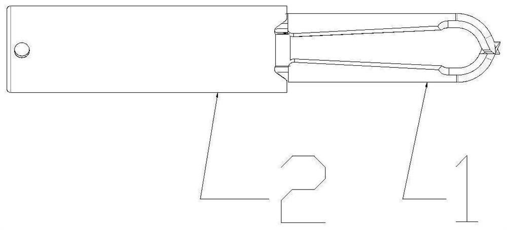
[0053] like figure 1 As shown, a clamping part of a clip device used with an endoscope includes a clip 1 and a clamp tube 2, the clip 1 is an elastic metal sheet, and the tails 140 of the two clips 1 are accommodated in the clamp tube 2 inside (such as image 3 and Figure 4 shown), such as figure 2 As shown, the tail portion 140 of the clip 1 is provided with an open hole 141 and an outwardly protruding first protrusion 142, the tail portion 140 of the clip 1 is flexibly connected with the front end of the push-pull seat 3 through the hole 141, and the rear of the push-pull seat 3 The end is connected to the mandrel 6, and the push-pull seat 3 is placed in the clamp tube 2 and can move forward and backward, such as Figure 5 As shown, the clamp tube 2 is provided with a stop portion for clamping the first protruding portion 142 of the tail 140 of the clip 1, and a detachable shackle 4 is connected to the rear of the clamp tube 2, and the shackle 4 Sleeved on the mandrel...


PUM


Abstract

The invention provides a clamp device used in cooperation with an endoscope and a clamping part of the clamp device. The clamping part comprises clamping pieces and a clamp tube, wherein the tail portions of the two clamping pieces are contained in the clamp tube; the tail portions of the clamping pieces are movably connected with the front end of a push-pull base; the clamp tube is provided witha stop part used for being connected with first protruding parts of the tail portions of the clamping pieces in a clamped mode; the rear end of the clamp tube is detachably connected with a hook ring;at least two elastic hook ring claws are arranged on the hook ring; first limiting parts corresponding to the hook ring claws are formed at the rear end of the clamp tube; the clamp tube is connectedwith the hook ring through the hook ring claws and the first limiting parts; and the hook ring is provided with a shielding part for shielding the stop part. According to the clamp device, the tail portions of the clamping pieces can be prevented from being clamped on the clamp tube in a repeated opening and closing adjustment process of the clamping pieces.

Description

technical field [0001] The invention relates to a clip device and its clamping part used in conjunction with an endoscope. Specifically, it is used for suturing surgical wounds under the endoscope to stop bleeding or prevent delayed hemostasis, or for temporarily clipping tissues to fix other equipment, or for purposes such as position marking. Background technique [0002] In the prior art, the following clamping devices or hemostatic forceps are used to clamp tissue to close the wound, stop bleeding or prevent delayed bleeding: [0003] In the patent document published by China with the patent application number CN201310272522.2, a hemostatic clip is disclosed in which the release method is broken by the connector, and the push-pull seat and the clip are fixed by the elastic reed on the clamp tube wall. , the fixing method of the release clip of the device is exposed, there is a risk of loosening, and the release process of the clip is cumbersome. [0004] In the patent ...

Claims


Application Information

Patent Timeline
IPC IPC(8): A61B17/122A61B17/128
CPCA61B17/1222A61B17/1285A61B2017/12004A61B17/083A61B17/10
Inventor 胡晓刚韩贯通高嵩
Owner ANREI MEDICAL HZ
Why Eureka
Try Eureka