

Casing structure between aero-engine turbines
An aero-engine and turbine technology, applied in combustion engines, engine components, machines/engines, etc., can solve problems such as cracks at the transition between the head of the support plate and the outer casing, fire safety, and difficulty in meeting requirements, and achieve assembly The effect of no interference with the decomposition process, good structural stability, and reasonable structure
- Summary
- Abstract
- Description
- Claims
- Application Information
AI Technical Summary
Problems solved by technology
Method used
Image

Examples
Embodiment Construction
[0056] In order to make the purpose, technical solution and advantages of the application more clear, the technical solution in the embodiment of the application will be described in more detail below in conjunction with the drawings in the embodiment of the application.
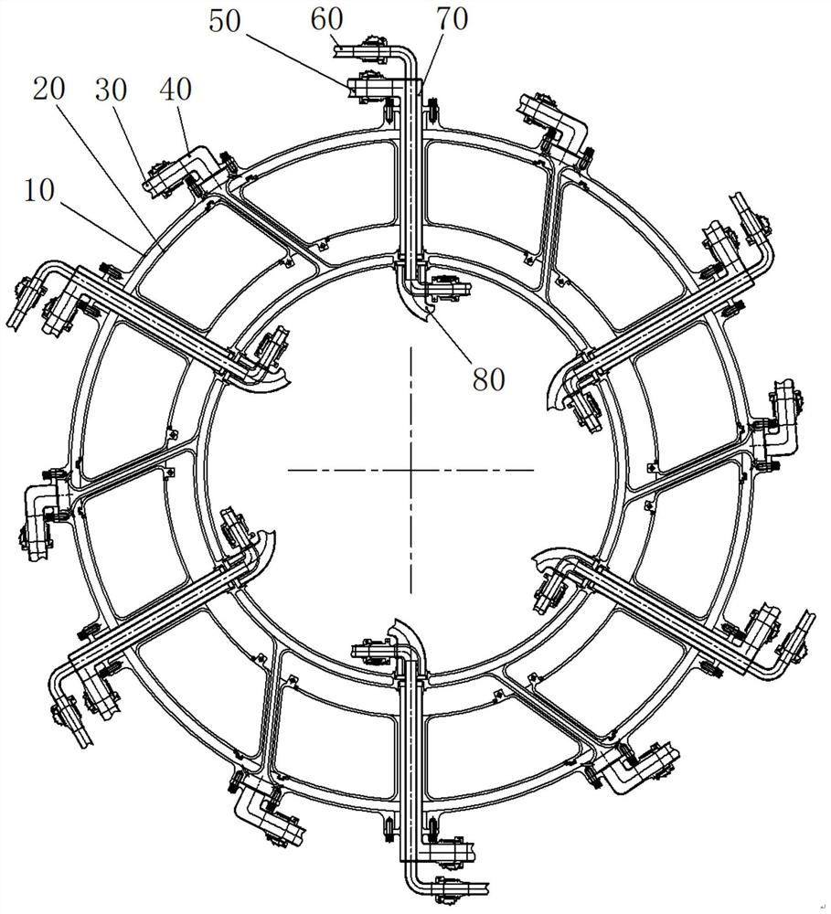
[0057] Aiming at the problems raised by the background technology, this application proposes a turbine inter-casing structure for aero-engines, aiming at improving the structural robustness of the inter-turbine casing, on the basis of realizing the circumferentially dispersed layout of bearing plates and pipeline channels On the one hand, it solves the technical problems of uncoordinated thermal deformation of the load-bearing frame, as well as the technical problems of thermal protection and failure protection of pipelines. At the same time, the new structure has engineering producibility and good assembly and disassembly.
[0058] Such as figure 1Shown is a schematic diagram of the structure of the inter-t...
PUM
 Abstract
Description
Claims
Application Information