
Liquid evaporator for air conditioner

A technology for evaporators and air conditioners, applied in evaporators/condensers, refrigeration and liquefaction, refrigeration components, etc., can solve problems such as poor separation effect, improve service life, increase circulation distance, and separate gas and liquid thorough effect

Pending Publication Date: 2020-09-15
张坤坤
View PDF7 Cites 0 Cited by
  • Summary
  • Abstract
  • Description
  • Claims
  • Application Information

AI Technical Summary

Problems solved by technology

[0004] The above-mentioned patent only uses a blocking part and a suction baffle installed at the suction port to separate the gas and liquid, but the separation effect is poor, and the excessive liquid refrigerant will enter the compression chamber before it becomes saturated vapor, causing The case of "hydraulic compression"

Method used


Image

  • Liquid evaporator for air conditioner
  • Liquid evaporator for air conditioner
  • Liquid evaporator for air conditioner

Examples


Embodiment Construction

[0024] The following will clearly and completely describe the technical solutions in the embodiments of the present invention with reference to the accompanying drawings in the embodiments of the present invention. Obviously, the described embodiments are only some, not all, embodiments of the present invention. Based on the embodiments of the present invention, all other embodiments obtained by persons of ordinary skill in the art without making creative efforts belong to the protection scope of the present invention.

[0025] see Figure 1-4 , the present invention provides the following technical solutions:

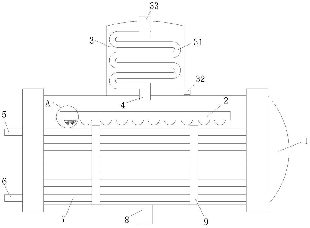
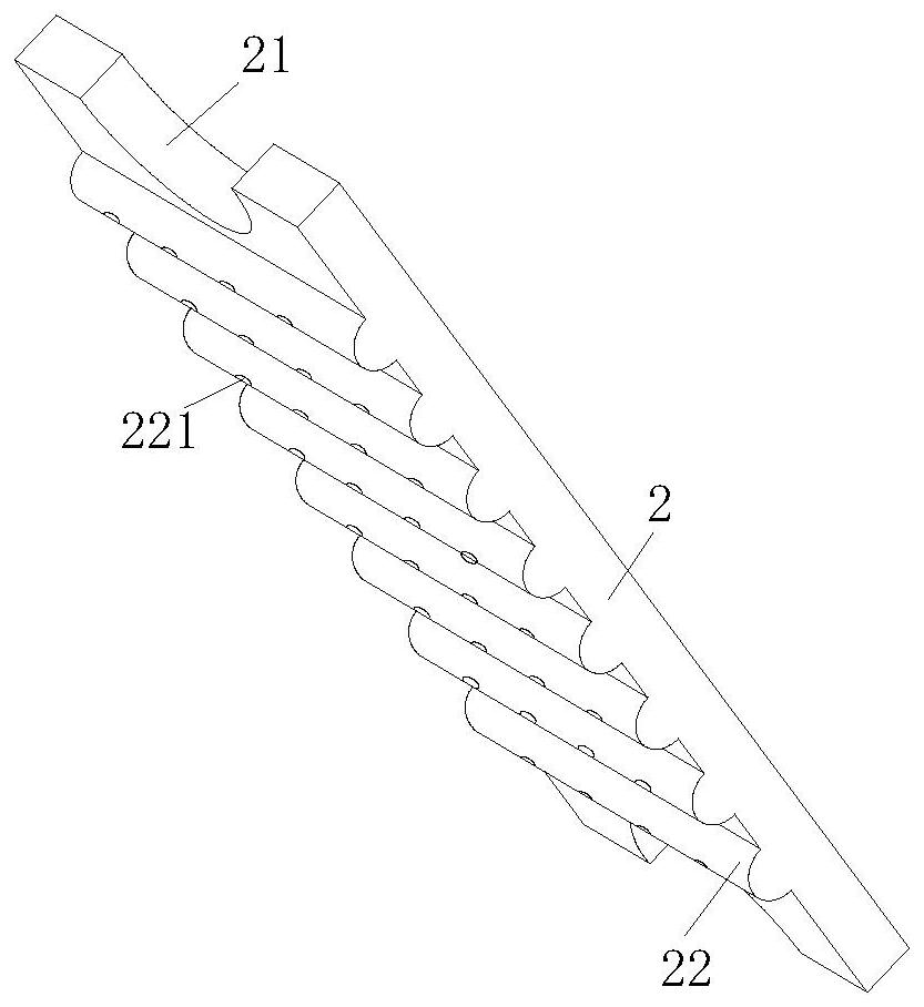
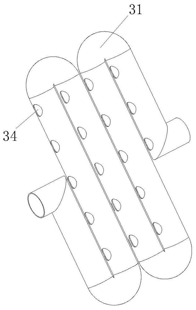
[0026] A liquid evaporator for an air conditioner, comprising a housing 1, characterized in that: the inside of the housing 1 is connected with a heat exchange tube 7, and the two ends of the heat exchange tube 7 are respectively connected with a cold water outlet 5 and a The cold water inlet 6, the cold water outlet 5 is located above the cold water inlet 6, the insi...


PUM


Abstract

The invention belongs to the technical field of air conditioner evaporators and particularly relates to a liquid evaporator for an air conditioner. The liquid evaporator comprises a shell, wherein a heat exchange pipe is arranged in the shell in a connected mode, the two ends of the heat exchange pipe are connected with a cold water outlet and a cold water inlet respectively, a liquid baffle is further arranged in the shell in a connected mode, the liquid baffle is located above the heat exchange pipe and is connected with the inner wall of the shell in a sealing mode, two ends of the liquid baffle are provided with gas outlets, a plurality of bumps are uniformly connected to the bottom of the liquid baffle, a liquid inlet is connected to the bottom of the shell, an evaporator gas outlet is connected to the top of the shell, and a separator is connected to a position, corresponding to the evaporator gas outlet, of the upper portion of the shell. According to the liquid evaporator, theliquid baffle connected with the inner wall of the shell is arranged above the heat exchange pipe in a welded mode, the two ends of the liquid baffle are provided with the gas outlets for gas circulation, the plurality of bumps of a semi-cylinder structure are connected to the bottom of the liquid baffle, therefore, the gas circulation distance is increased, and gas and liquid are separated more thoroughly.

Description

technical field [0001] The invention belongs to the technical field of air conditioner evaporators, and in particular relates to a liquid evaporator for an air conditioner. Background technique [0002] Reliability and stability are the basic prerequisites for the design of large commercial chillers. Screw chillers are no exception. Generally, the screw unit allows part of the suction to carry liquid. The advantage of this is that part of the liquid refrigerant sucked in will cool down the motor at the suction end of the compressor, and the refrigerant will absorb heat and become saturated vapor, and then be sucked into the compression chamber by the screw compressor Compression recirculation. However, if there is too much liquid refrigerant to become saturated vapor, it will enter the compression chamber. Because of the incompressibility of the liquid, if it is forced to compress, the screw and bearing will bear a very large force. We generally call it "hydraulic compress...

Claims


Application Information

Patent Timeline
Patent Type & Authority Applications(China)
IPC IPC(8): F25B39/02F25B43/00
CPCF25B39/02F25B43/00F25B2339/0242
Inventor 张坤坤高璐
Owner 张坤坤
Learn More