Paraffin removal device for oil wells

A technology for removing wax and oil wells. It is used in isolation devices, cleaning appliances, wellbore/well components, etc. It can solve problems such as low heating efficiency, and achieve the effect of improving heat utilization and increasing circulation distance.

Inactive Publication Date: 2015-06-10
CHINA PETROLEUM & CHEM CORP +1
View PDF7 Cites 0 Cited by
  • Summary
  • Abstract
  • Description
  • Claims
  • Application Information

AI Technical Summary

Problems solved by technology

[0004] The purpose of the present invention is to provide a wax removal device that can not only make full use of the heat of the burner flame, but also make full use of the heat of the flue gas generated by the flame, so as to solve the problem of low heating efficiency of the existing wax removal equipment

Method used


Image

  • Paraffin removal device for oil wells
  • Paraffin removal device for oil wells
  • Paraffin removal device for oil wells

Examples


Embodiment Construction

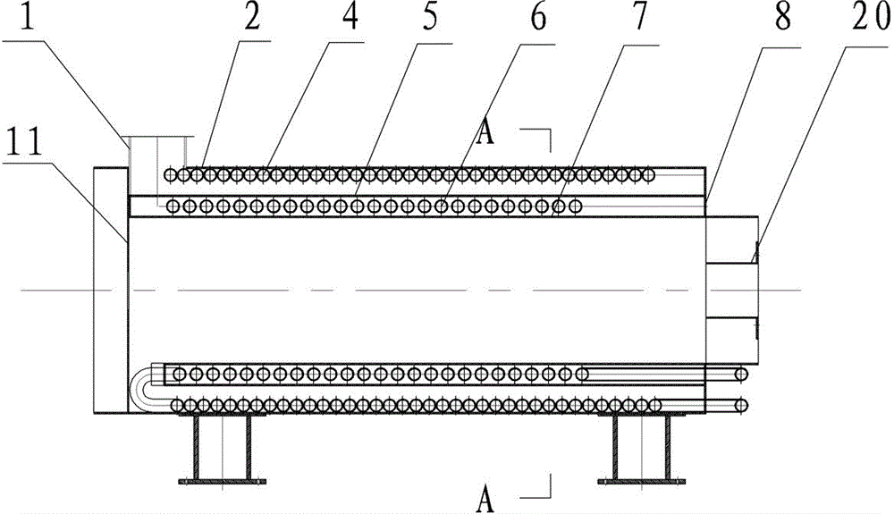
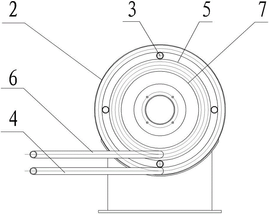
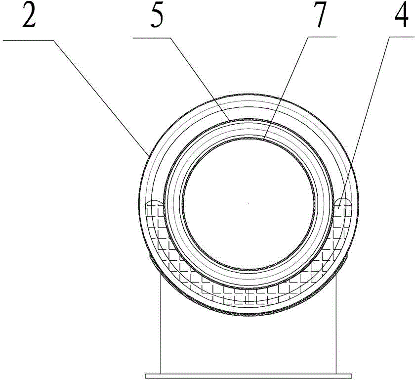
[0024] The embodiment of oil well wax removing device of the present invention: comprise heating body, the structure of heating body is as follows Figure 1-5 As shown, the heating body includes a cylinder body 2, an outer bladder 5 is sleeved in the inner gap of the cylinder body 2, and an inner bladder 7 is sleeved in the inner gap of the outer bladder 5, and the cylinder body 2, the outer bladder 5, and the inner bladder 7 are all the same A cylindrical structure where the shaft is set. The front and rear ends of the cylinder 2 are respectively fixed with head baffles sealing the cylinder 2, which are respectively the front head baffle 8 and the rear head baffle 11, the outer bladder 5 and the inner bladder 7 The front and rear ends are respectively sealed and fixedly connected with the respective corresponding head baffles, and the front end of the inner tank 7 protrudes from the front head baffle 8, so that the gap between the cylinder body 2 and the outer tank 5, the out...


PUM


Abstract

The invention discloses a paraffin removal device for oil wells. The paraffin removal device comprises a barrel and an outer container which is sheathed in the barrel in a clearance manner; an inner container is sheathed in the outer container in a clearance manner; a front seal head baffle and a rear seal head baffle, which are fixedly connected with the end parts of the outer container and the inner container in a sealing manner, are fixed at the front end and the back end of the barrel; a through hole, through which a spray nozzle of a burner is extended into the inner container, is arranged on the front seal head baffle; an outer container gap is arranged at the rear end of the outer container; an inner container gap is arranged at the rear end of the inner container; the outer container gap and the inner container gap form a first gap; an inner guiding pipe is arranged between the outer container and the inner container; an outer guiding pipe, which is communicated with the inner guiding pipe at the first gap, is arranged between the barrel and the outer container; and a chimney, which is communicated with a gap between the barrel and the outer container, is arranged on the barrel. For the paraffin removal device, the inner guiding pipe is heated by using heat generated by high-temperature fire, simultaneously, the outer guiding pipe is directly heated by using heat generated by a flue gas, thereby the heat of the high-temperature fire is fully used, and simultaneously the heat of flue gas is effectively used. The paraffin removal device has high heat efficiency and compact structure.

Description

technical field [0001] The invention relates to a wax removal device for oil wells. Background technique [0002] In the development and production of oil fields, due to the high wax content, thick oil and high viscosity of oil wells, it is easy to cause high back pressure, pipeline blockage and wellbore wax deposition, which will increase the friction resistance of sucker rods, increase wear and power consumption, and reduce flow , affecting the normal production or output of the oil well, wax and scale removal must be carried out regularly or irregularly to ensure the normal production of the oil well. [0003] Chinese patent CN102022097A discloses a multifunctional wax removal equipment for oilfields. The equipment uses a boiler as a platform and adopts a thermal wax removal method. It includes a cylinder and an inner tank inside the cylinder. The front and rear inner head baffles are respectively fixed at the positions, and the front and rear inner head baffles cooperat...

Claims


Application Information

Patent Timeline
Patent Type & Authority Patents(China)
IPC IPC(8): E21B37/00E21B36/02
Inventor 房胤娄和宇李洪林王海平邢亚生贾朝阳
Owner CHINA PETROLEUM & CHEM CORP
Why Eureka
Try Eureka