Gas purification and separation device with automatic liquid level balance and fixed-point pipetting

An automatic balance and separation device technology, which is applied in the direction of using liquid separation agent, separation method, and separation of dispersed particles, can solve problems such as time required, influence on purification efficiency, liquid shaking of fine dust accumulation layer, etc., to achieve sufficient time and save power source effect

Active Publication Date: 2021-11-16
NANTONG FLECK FLUID EQUIP
View PDF0 Cites 0 Cited by
  • Summary
  • Abstract
  • Description
  • Claims
  • Application Information

AI Technical Summary

Problems solved by technology

A large amount of dust enters the liquid medium. If it cannot be removed in time, the total solid content of the solution will increase, causing foaming and deposition on the surface of the defoaming layer filler, which will increase the resistance of the absorption equipment or cause liquid flooding, reducing the production capacity.
[0003] When the existing purification equipment deals with the flooding phenomenon, the liquid level is monitored through the sensor, and the passing air bubbles emerge in the purification liquid, which makes the liquid in the fine dust accumulation layer vibrate, often resulting in false monitoring;
[0004] In addition, in order to balance the liquid level, only by opening the valve in a timely manner, the suspended fine dust after purification will be discharged together with the released liquid, and the rest will be mixed in the purification liquid, and it will take time to purify again, thus affecting the purification. efficiency

Method used

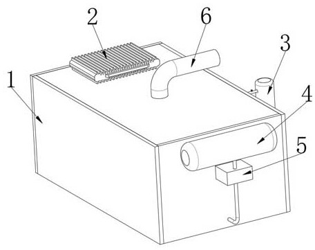

Image

  • Gas purification and separation device with automatic liquid level balance and fixed-point pipetting
  • Gas purification and separation device with automatic liquid level balance and fixed-point pipetting
  • Gas purification and separation device with automatic liquid level balance and fixed-point pipetting

Examples


Embodiment Construction

[0031] The following will clearly and completely describe the technical solutions in the embodiments of the present invention with reference to the accompanying drawings in the embodiments of the present invention. Obviously, the described embodiments are only some, not all, embodiments of the present invention.

[0032] In describing the present invention, it should be understood that the terms "upper", "lower", "front", "rear", "left", "right", "top", "bottom", "inner", " The orientation or positional relationship indicated by "outside", etc. is based on the orientation or positional relationship shown in the drawings, and is only for the convenience of describing the present invention and simplifying the description, rather than indicating or implying that the referred device or element must have a specific orientation, so as to Specific orientation configurations and operations, therefore, are not to be construed as limitations on the invention.

[0033] refer to Figure ...


PUM


Abstract

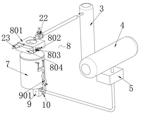
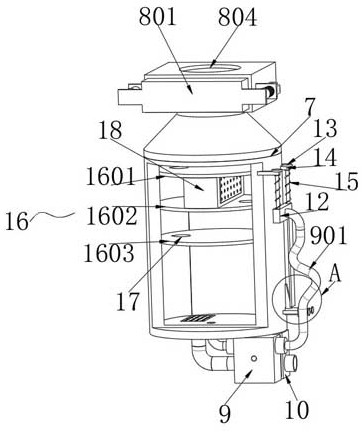
The invention discloses a gas purification and separation device with automatic liquid level balance and fixed-point pipetting, which includes a separation device housing, a purification tank is provided inside the separation device housing, and an exhaust gas tank is provided on one side of the separation device housing. And the bottom of the waste gas tank and the purification tank are connected through a branch pipe, and the bottom of the purification tank is respectively fixed with a liquid impeller pump and a gas impeller pump, and the impeller shafts of the two pass through their side walls and are connected by a connecting component for The gas impeller pump drives the liquid impeller pump to work, and both the liquid impeller pump and the gas impeller pump communicate with the bottom of the purification tank through branch pipes, and the branch pipe between the waste gas tank and the purification tank is also connected with a pressure limiting valve. The invention relates to the technical field of gas purification and separation. The separation device can accurately determine the liquid flooding phenomenon, and can improve the purification time of the bubbles in the purification liquid by fully breaking up the bubbles in the exhaust gas to ensure the adequacy of the purification. .

Description

technical field [0001] The invention relates to the technical field of gas purification and separation, in particular to a gas purification and separation device with automatic liquid level balance and fixed-point pipetting. Background technique [0002] During the manufacture and transportation of synthetic gas, natural gas, city gas and other gases, due to the corrosion and wear of raw materials and pipe walls, they usually contain a certain amount of dust, organic or inorganic sulfides and condensate of the saturated liquid phase in the gas. . A large amount of dust enters the liquid medium. If it cannot be removed in time, the total solid content of the solution will increase, causing foaming and deposition on the surface of the defoaming layer filler, which will increase the resistance of the absorption equipment or cause liquid flooding, resulting in a reduction in production capacity. [0003] When the existing purification equipment deals with the flooding phenomeno...

Claims


Application Information

Patent Timeline
Patent Type & Authority Patents(China)
IPC IPC(8): B01D47/02
CPCB01D47/021
Inventor 马燕
Owner NANTONG FLECK FLUID EQUIP
Why Eureka
Try Eureka