Rigid body rotation dynamics experiment device
An experimental device and dynamics technology, applied in the field of experimental teaching, can solve problems such as unfavorable exploration and cognition of students' interest, less equipment, etc., and achieve the effects of clear reflection of physical principles and phenomena, low cost, and simple structure of the device
- Summary
- Abstract
- Description
- Claims
- Application Information
AI Technical Summary
Problems solved by technology
Method used
Image
Examples
Embodiment 1
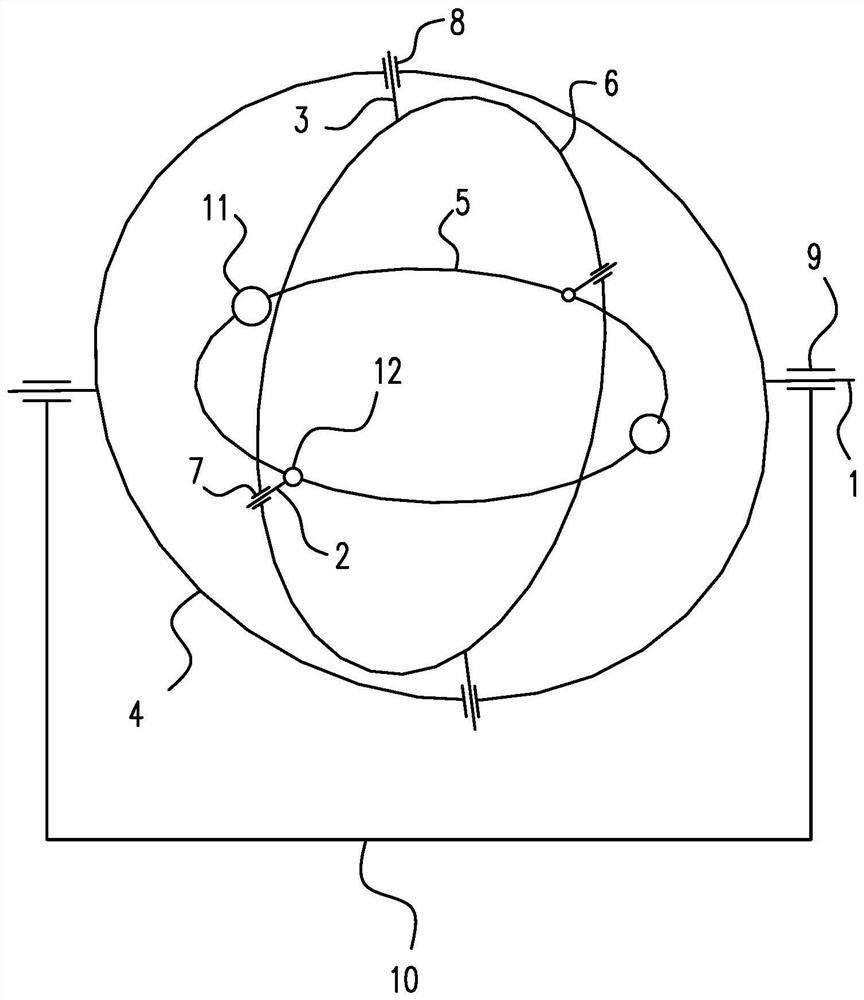
[0029] like figure 1 As shown, a rigid body rotational dynamics experiment device includes X-axis 1 , Y-axis 2 , and Z-axis 3 perpendicular to each other, and X-frame 4 , Y-frame 5 , and Z-frame 6 that are fixedly connected to these rotation axes.
[0030] The X frame and the Z frame are connected through the Z axis rotation, the Z frame rotates within the X frame, the Z frame and the Y frame are connected through the Y axis rotation, and the Y frame rotates within the Z frame.
[0031] The Z frame is provided with a Z frame bearing 7, and the X frame is provided with an X frame bearing 8. The Y axis is supported on the Z frame bearing, the Z axis is supported on the X frame bearing, and the X axis is supported on an external bearing. 9, the position of the external bearing is fixed on the fixed bracket 10, so that each frame can freely rotate around its own axis, so that the Y frame can freely rotate in three-dimensional space with three degrees of freedom.
[0032] The X fr...
Embodiment 2
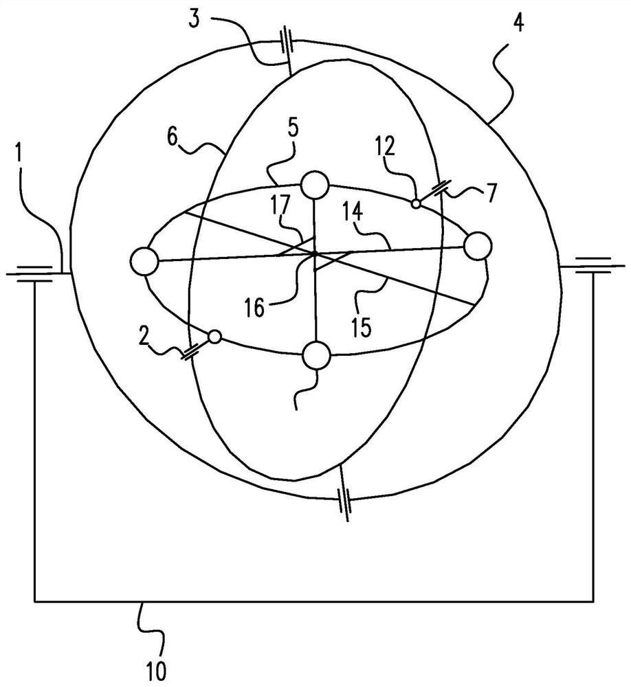
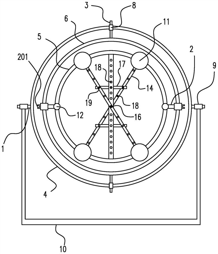
[0038] like figure 2 , 3, 4, and 5, different from the above-mentioned embodiment, the large mass block is set to four, and the large mass block is a spherical slider that slides on the Y frame, that is, the spherical slider has a holes, wherein every two central symmetrical mass blocks are connected by a connecting rod 14, the Y frame is provided with a positioning rod 15 perpendicular to the Y axis, the center of the positioning rod is located at the center of the Y frame, and the center of the connecting rod is in line with the The center of the positioning rod is connected by rotating shaft rotation. For example, a connecting shaft 16 perpendicular to the positioning rod is fixed at the center of the positioning rod, and the connecting shaft and the positioning rod are vertically cross-connected. The connecting shafts on both sides of the positioning rod are respectively rotated to connect different connecting rods. A shaft hole 141 can be set on the connecting rod, and ...
Embodiment 3
[0044] like Image 6 , 7 , 8, different from the above-mentioned embodiments, the two ends of the support rod are connected with sliders 20 that rotate, and the sliders slide on the connecting rod, which is equivalent to the connecting rod slider mechanism. The middle part of the support rod and the positioning rod Temporary connection through a detachable connection device, for example, the temporary connection method of positioning holes and positioning pins in Embodiment 2 can be used, and of course other connection methods, such as the connection method of bolts and screw holes, can also be used.
PUM
 Abstract
Description
Claims
Application Information
 - R&D
- Intellectual Property
- Life Sciences
- Materials
- Tech Scout
- Unparalleled Data Quality
- Higher Quality Content
- 60% Fewer Hallucinations
Browse by: Latest US Patents, China's latest patents, Technical Efficacy Thesaurus, Application Domain, Technology Topic, Popular Technical Reports.
© 2025 PatSnap. All rights reserved.Legal|Privacy policy|Modern Slavery Act Transparency Statement|Sitemap|About US| Contact US: help@patsnap.com


