A Rigid Body Rotational Dynamics Experimental Device

An experimental device and dynamics technology, applied in the field of experimental teaching, can solve the problems of less equipment and unfavorable students' interesting exploration and cognition, and achieve the effects of low cost, clear reflection of physical principles and phenomena, and convenient operation

Active Publication Date: 2022-05-17
NINGBO UNIV
View PDF9 Cites 0 Cited by
  • Summary
  • Abstract
  • Description
  • Claims
  • Application Information

AI Technical Summary

Problems solved by technology

[0002] Rigid body rotational dynamics is a complex and widely used subject. It is difficult to observe intuitively in reality. Theories related to the optional stability of rigid body rotational dynamics, gyroscope mechanics theory, etc. have few related equipment, and most of the existing ones are more sophisticated. Complicated, not conducive to students' interesting exploration and cognition

Method used


Image

  • A Rigid Body Rotational Dynamics Experimental Device
  • A Rigid Body Rotational Dynamics Experimental Device
  • A Rigid Body Rotational Dynamics Experimental Device

Examples


Embodiment 1

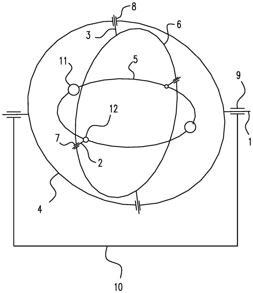
[0029] Such as figure 1 As shown, a rigid body rotational dynamics experiment device includes X-axis 1 , Y-axis 2 , and Z-axis 3 perpendicular to each other, and X-frame 4 , Y-frame 5 , and Z-frame 6 that are fixedly connected to these rotation axes.

[0030] The X frame and the Z frame are connected through the Z axis rotation, the Z frame rotates within the X frame, the Z frame and the Y frame are connected through the Y axis rotation, and the Y frame rotates within the Z frame.

[0031] The Z frame is provided with a Z frame bearing 7, and the X frame is provided with an X frame bearing 8. The Y axis is supported on the Z frame bearing, the Z axis is supported on the X frame bearing, and the X axis is supported on an external bearing. 9, the position of the external bearing is fixed on the fixed bracket 10, so that each frame can freely rotate around its own axis, so that the Y frame can freely rotate in three-dimensional space with three degrees of freedom.

[0032] The X...

Embodiment 2

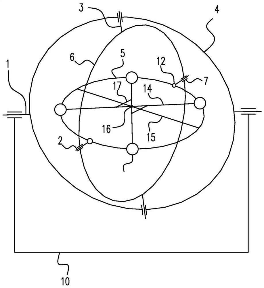
[0038] Such as figure 2 , 3, 4, and 5, different from the above-mentioned embodiment, the large mass block is set to four, and the large mass block is a spherical slider that slides on the Y frame, that is, the spherical slider has a holes, wherein every two central symmetrical mass blocks are connected by a connecting rod 14, the Y frame is provided with a positioning rod 15 perpendicular to the Y axis, the center of the positioning rod is located at the center of the Y frame, and the center of the connecting rod is in line with the The center of the positioning rod is connected by rotating shaft rotation. For example, a connecting shaft 16 perpendicular to the positioning rod is fixed at the center of the positioning rod, and the connecting shaft and the positioning rod are vertically cross-connected. The connecting shafts on both sides of the positioning rod are respectively rotated to connect different connecting rods. A shaft hole 141 can be set on the connecting rod, a...

Embodiment 3

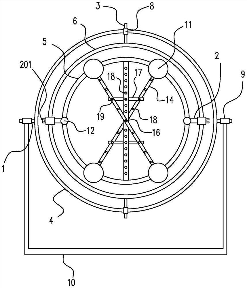
[0044] Such as Figure 6 , 7 , 8, different from the above-mentioned embodiments, the two ends of the support rod are connected with sliders 20 that rotate, and the sliders slide on the connecting rod, which is equivalent to the connecting rod slider mechanism. The middle part of the support rod and the positioning rod Temporary connection through a detachable connection device, for example, the temporary connection method of positioning holes and positioning pins in Embodiment 2 can be used, and of course other connection methods, such as the connection method of bolts and screw holes, can also be used.


PUM


Abstract

The invention provides a rigid body rotation dynamics experiment device, which relates to a mechanics experiment device. It solves the problem of lack of simple rigid body rotational dynamics experimental devices in the prior art. This experimental device includes X-axis, Y-axis, and Z-axis which are perpendicular to each other. The rotation position of the X-axis is fixed. The X-axis is connected to the X frame. It is connected with the Y frame through the Y axis rotation. The Y frame rotates in the Z frame. The Y frame is a circular frame. There are two large mass blocks symmetrical about the center on the Y frame. The Y axis connection of the Y frame is symmetrical about the center. The setup has two small masses. The present invention uses a three-degree-of-freedom rotating device to provide a simulation model for the spin dynamics research of a rigid body, so that the phenomenon of the rigid body's spin-stabilized intermediate axis can be clearly observed; by setting the mass block in an adjustable manner, thereby increasing Functionality of the experimental setup.

Description

technical field [0001] The invention belongs to the technical field of experiment teaching, and relates to a mechanical experiment device, in particular to a rigid body dynamics experiment device. Background technique [0002] Rigid body rotational dynamics is a complex and widely used subject. It is difficult to observe intuitively in reality. Theories related to the optional stability of rigid body rotational dynamics, gyroscope mechanics theory, etc. have few related equipment, and most of the existing ones are more sophisticated. Complexity is not conducive to students' interesting exploration and cognition. [0003] For example, the tennis racket theorem (also known as the intermediate axis theorem) in the rigid body self-selected stability theory is the solution of Euler's equation when describing the motion of a free rigid body in classical mechanics. The rigid body can rotate around three different principal axes, and the three moments of inertia Not equal to each o...

Claims


Application Information

Patent Timeline
Patent Type & Authority Patents(China)
IPC IPC(8): G09B23/10
CPCG09B23/10
Inventor 李淑欣苏云帅鲁思渊余丰曹均
Owner NINGBO UNIV
Why Eureka
Try Eureka