Deflection coil for ultra large deflection float CRT

A deflecting coil and picture tube technology, applied in the direction of electrode device and related components, can solve problems such as difficulty and difficulty in small light spots, and achieve the effect of reducing cost

Inactive Publication Date: 2003-07-30
SHANGHAI JIAO TONG UNIV
View PDF0 Cites 0 Cited by
  • Summary
  • Abstract
  • Description
  • Claims
  • Application Information

AI Technical Summary

Problems solved by technology

However, as the quality factor increases, the light spot and image quality will decrease, so the larger the deflection angle is, the more difficult it is to obtain a small quality factor, which means that with the increase of the deflection angle, it is more difficult to obtain a small light spot. Find similar or consistent literature reports with the subject of the present invention

Method used


Image

  • Deflection coil for ultra large deflection float CRT
  • Deflection coil for ultra large deflection float CRT
  • Deflection coil for ultra large deflection float CRT

Examples


Embodiment Construction

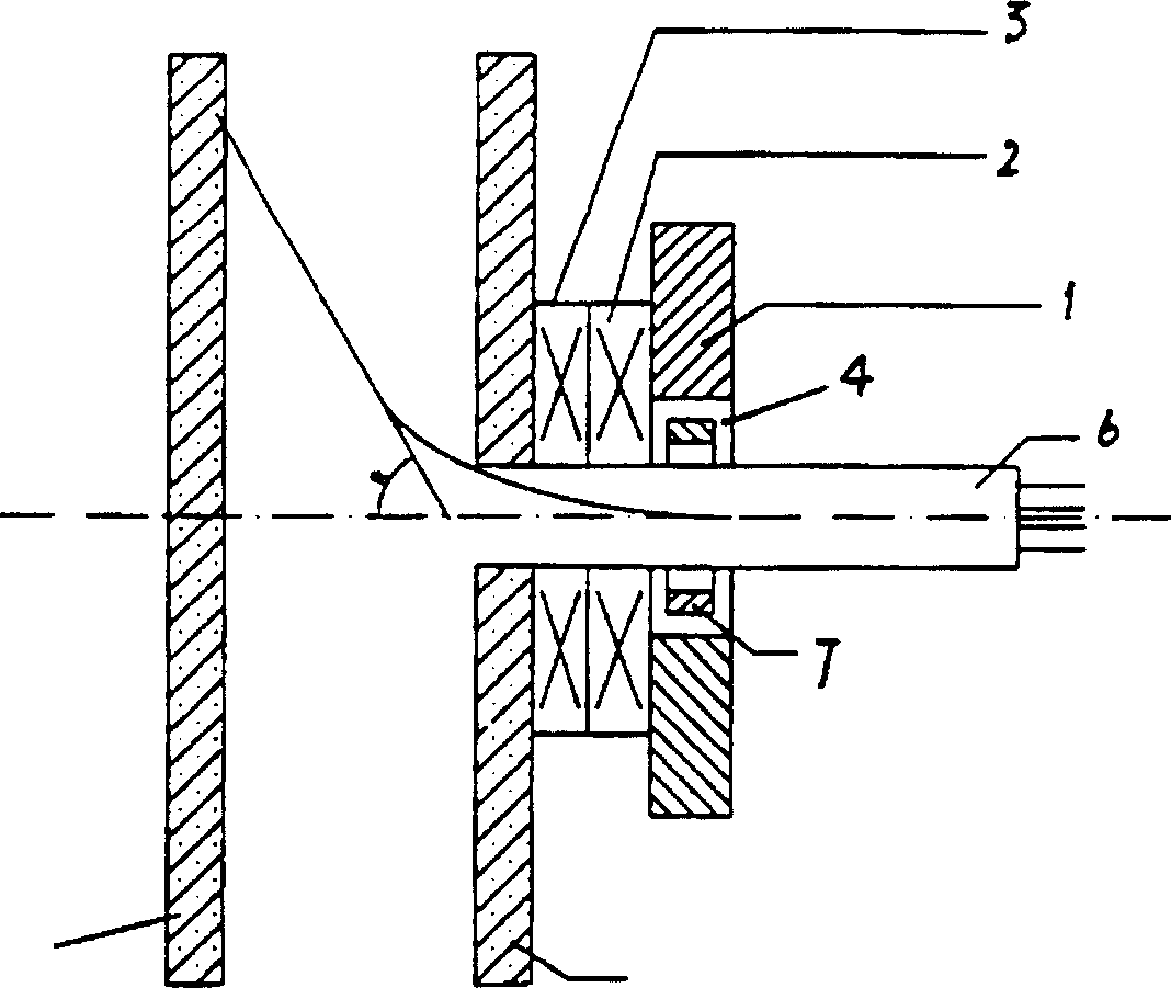
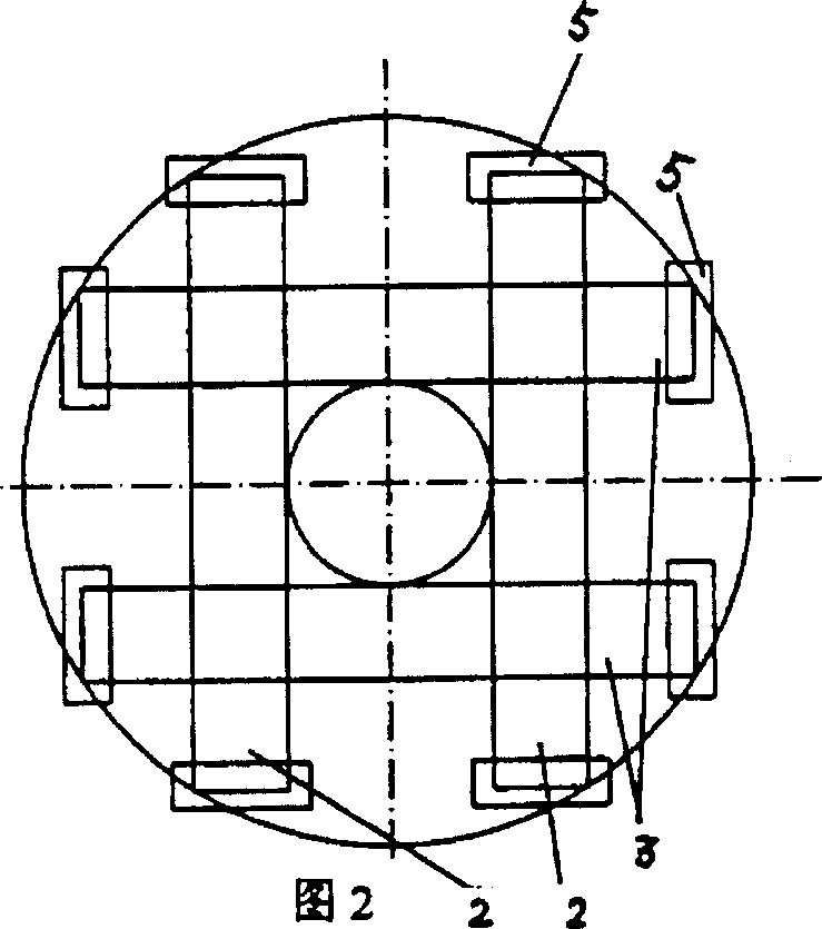
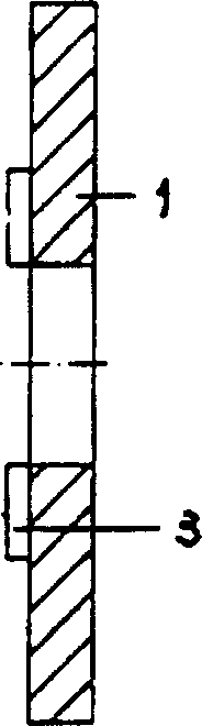
[0018] like figure 1 , Figure 2 and image 3 As shown, the present invention mainly includes: a ferrite core 1, a frame deflection coil 2 and a line deflection coil 3. On a flat circular or rectangular ferrite core 1, a pair of The plane rectangular frame deflection coil 2 and a pair of plane rectangular line deflection coils 3 form a basic plane deflection coil pattern. The diameter of the central hole 4 of the ferrite core 1 is determined by the diameter of the electron gun 6 . A rectangular correction coil 5 is added to the short arm of each rectangular coil to correct the pincushion distortion of the picture, or a magnetic field shielding plate is used to eliminate the pincushion distortion. The deflection angle R has focusing characteristics from 0° to 80°.

[0019] like figure 1 , Figure 4 and Figure 5 As shown, a small circular or square ferrite core 8 is placed in the central hole 4 of the circular ferrite core 1, and a pair of frame and row pre-deflection coil...


PUM


Abstract

A deflection coil for the flat CRT cathod ray tube with very large deflection is composed of circular or rectangular ferrite core, a pair of rectangular flat frame deflection coils and a pair of rectangular flat line deflection coils, which are arranged on the ferrite core in mutually perpendicular mode.

Description

technical field [0001] The invention relates to a deflection coil of a flat picture tube, in particular to a deflection coil of a super large deflection flat picture tube, which belongs to the field of picture tubes of television technology. Background technique [0002] Since the 1990s, LCD, plasma and other flat-panel display devices have made great achievements, posing challenges to picture tubes, and the market competition has become increasingly fierce. Large (long and large cone), relatively bulky and other shortcomings, the international picture tube research institutions have been doing everything possible to improve these shortcomings. The deflection angle gradually increases from the earliest 36° to 45°, 50°, 53°, and 70°. Currently, it is generally 90°, 100°, and 110°. Increasing the deflection angle will cause serious defocusing of the electron beam during scanning, and the increase of the spot size will greatly reduce the sharpness of the image edge. The key t...

Claims


Application Information

Patent Timeline
Patent Type & Authority Patents(China)
IPC IPC(8): H01J29/76
Inventor 张可南梁国恩林书铨王妙康唐敦乙黄保麟
Owner SHANGHAI JIAO TONG UNIV
Why Eureka
Try Eureka