
Magnetic stirrer

A magnetic stirrer and controller technology, applied in chemical instruments and methods, dissolving, mixing machines, etc., can solve problems such as high cost, easy oil leakage noise of reducer, and inability to meet clean and hygienic requirements

Pending Publication Date: 2020-09-18
浙江博业机械科技有限公司
View PDF0 Cites 0 Cited by
  • Summary
  • Abstract
  • Description
  • Claims
  • Application Information

AI Technical Summary

Problems solved by technology

[0002] The existing magnetic stirrer on the market is driven by a motor with a reducer (or motor) to drive the outer rotor with permanent magnets, and then the outer rotor drives the inner rotor in the container to rotate. The inner rotor is equipped with paddles for stirring. Due to the need to meet different working conditions and adjust the speed of the blades, the motor needs to be equipped with a reducer or the speed can be adjusted through a frequency converter. This will cost more, the reducer is prone to oil leakage and loud noise, and it cannot meet the requirements of cleanliness and sanitation. Require

Method used


Image

  • Magnetic stirrer
  • Magnetic stirrer

Examples


Embodiment Construction

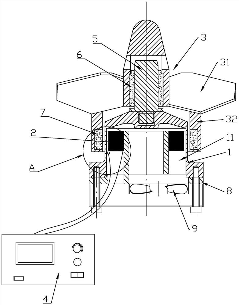
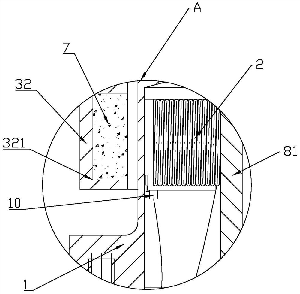
[0019] Such as Figure 1-Figure 2 As shown, a magnetic stirrer includes a spacer 1, a stator coil 2, a rotor 3 and a controller 4. The spacer 1 is welded to the container to be stirred and fixed as a whole to ensure the seal without leakage. The stator coil 2 is installed on In the spacer 1, the controller 4 supplies power to the stator coil 2, and one end of the spacer 1 is fixed or integrally provided with a support shaft 5, and the rotor 3 is rotated on the support shaft 5 through a silicon carbide bearing 6, and the rotor 3 is fixed or integrally provided There are paddles 31, and the rotor 3 is provided with an annular magnet 7 corresponding to the stator coil 2, and the stator coil 2 can drive the rotor 3 to rotate to realize stirring by the paddles 31. The controller 4 mainly plays the role of power supply and switch control, and the controller 4 is a conventional technical means in the field, so it will not be specifically introduced in this article.

[0020] In this ...


PUM


Abstract

The invention relates to a magnetic stirrer. The magnetic stirrer comprises an isolation sleeve, a stator coil, a rotor and a controller. The isolation sleeve is connected with an external container,the stator coil is installed in the isolation sleeve, the controller supplies power to the stator coil, a supporting shaft is arranged at one end of the isolation sleeve, the rotor is rotatably arranged on the supporting shaft, blades are fixedly or integrally arranged on the rotor, an annular magnet is arranged at the position, corresponding to the stator coil, of the rotor, and the stator coil is powered on to drive the rotor to rotate to achieve blade stirring. By adopting the scheme, the magnetic stirrer overcomes the defects in the prior art, and has the advantages of cost reduction, no leakage and low noise.

Description

technical field [0001] The invention relates to a magnetic stirrer. Background technique [0002] The existing magnetic stirrer on the market is driven by a motor with a reducer (or motor) to drive the outer rotor with permanent magnets, and then the outer rotor drives the inner rotor in the container to rotate. The inner rotor is equipped with paddles for stirring. Due to the need to meet different working conditions and adjust the speed of the blades, the motor needs to be equipped with a reducer or the speed can be adjusted through a frequency converter. This will cost more, the reducer is prone to oil leakage and loud noise, and it cannot meet the requirements of cleanliness and sanitation. Require. Contents of the invention [0003] The invention overcomes the disadvantages of the prior art and provides a magnetic stirrer with reduced cost, no leakage and low noise. [0004] In order to achieve the above object, the technical solution adopted in the present inventio...

Claims


Application Information

Patent Timeline
Patent Type & Authority Applications(China)
IPC IPC(8): B01F13/08
CPCB01F33/453
Inventor 朱家伟朱生
Owner 浙江博业机械科技有限公司
Learn More