Quick disassembly and assembly type die-casting mold ejection mechanism

A technology of ejection mechanism and die-casting mold, which is applied in the field of die-casting molds, can solve the problems of affecting the production efficiency of die-casting, inconvenient disassembly and installation, and long downtime, etc., and achieves the effects of quick assembly and disassembly, convenient assembly, and improved die-casting efficiency

Active Publication Date: 2020-09-18
广东鸿图武汉压铸有限公司 +1
View PDF11 Cites 0 Cited by
  • Summary
  • Abstract
  • Description
  • Claims
  • Application Information

AI Technical Summary

Problems solved by technology

[0003] refer to figure 1 , the ejector mechanism of the existing die-casting mold includes an ejector rod 1a, a lock nut 1b, a screw washer 1c, an ejector plate 1d and a connecting bolt 1e, wherein the ejector rod 1a is provided with a certain length of internal thread, and the connecting bolt 1e extends into the inside of the ejector rod 1a after passing through the screw washer 1c, the ejector plate 1d and the lock nut 1b, thereby locking the ejector plate 1d and the ejector rod 1a together; since the ejector mechanism of the die-casting mold is working , the ejector plate 1d will drive the ejector rod 1a to move together through the connecting bolt 1e. When the ejector rod 1a is working, the external thread of the connecting bolt 1e and the internal thread of the ejector rod 1a will pull each other, so that the connecting bolt 1e and the ejector rod 1a are subjected to a large pulling force. Under the action of the pulling force, the thread on the connecting bolt 1e and the ejector rod 1a will be deformed and slipped, causing the connecting bolt 1e and the ejector rod 1a to be locked in a large area. If it is fixed together, it is not easy to disassemble and install. If the ejector rod 1a needs to be replaced, the downtime will be longer, which will directly affect the production efficiency of die casting and cause the production capacity to fail to meet the standard.

Method used


Image

  • Quick disassembly and assembly type die-casting mold ejection mechanism
  • Quick disassembly and assembly type die-casting mold ejection mechanism

Examples


Embodiment Construction

[0021] In order to make the object, technical solution and advantages of the present invention clearer, the present invention will be further described in detail below in conjunction with the accompanying drawings and embodiments. It should be understood that the specific embodiments described here are only used to explain the present invention, not to limit the present invention. In addition, the technical features involved in the various embodiments of the present invention described below can be combined with each other as long as they do not constitute a conflict with each other.

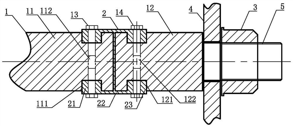
[0022] refer to figure 2 , a quick-release die-casting mold ejection mechanism, including an ejector rod 1, a concave block 2, a fixed nut 3 and an ejector plate 4, wherein,

[0023] The ejector rod 1 includes a first connecting head 11 and a second connecting head 12, the first connecting head 11 and the second connecting head 12 are cylindrical as a whole and they are arranged coaxially;

...


PUM


Abstract

The invention discloses a quick disassembly and assembly type die-casting mold ejection mechanism. The ejection mechanism comprises an ejection rod, concave clamping blocks, a fixing nut and an ejection plate; the ejection rod comprises a first connector and a second connector, first clamping grooves and first locking threaded holes are formed in the end, close to the second connector, of the first connector, and second clamping grooves and second locking threaded holes are formed in the end, close to the first connector, of the second connector; and the concave clamping blocks comprise firstclamping tables, clamping table connecting parts and second clamping tables which are integrally formed, a screw is integrally formed at the end, away from the first connector, of the second connector, and the ejection plate is locked on the second connector through the fixing nut. The quick disassembly and assembly type die-casting mold ejection mechanism can effectively solve the problem that the screw is difficult to disassemble due to screw loose locking, and the ejector rod and the ejector plate are easy to replace and disassemble so that the die-casting efficiency can be greatly improved, the mold replacing efficiency is reduced, and meanwhile, the time for abnormally stopping operation is shortened.

Description

technical field [0001] The invention belongs to the technical field of die-casting molds, and more specifically relates to a die-casting mold ejection mechanism. Background technique [0002] The die-casting mold is a metal mold used to form castings in the die-casting forming process. After the die-casting is formed, it is necessary to use the ejector rod of the ejector mechanism to push the injection-molded product out of the die-casting mold for demoulding. [0003] refer to figure 1 , the ejector mechanism of the existing die-casting mold includes an ejector rod 1a, a lock nut 1b, a screw washer 1c, an ejector plate 1d and a connecting bolt 1e, wherein the ejector rod 1a is provided with a certain length of internal thread, and the connecting bolt 1e extends into the inside of the ejector rod 1a after passing through the screw washer 1c, the ejector plate 1d and the lock nut 1b, thereby locking the ejector plate 1d and the ejector rod 1a together; since the ejector mec...

Claims


Application Information

Patent Timeline
Patent Type & Authority Applications(China)
IPC IPC(8): B22D17/22
CPCB22D17/2236
Inventor 黄明军余波王科
Owner 广东鸿图武汉压铸有限公司
Why Eureka
Try Eureka