
Spiral tool setting mechanism and method for precise numerical control gantry grooving machine

A precision numerical control and slotting machine technology, applied in the direction of automatic control devices, metal processing machinery parts, measuring/indicating equipment, etc., can solve the problems of low slotting efficiency, weak versatility, and inability to flexibly adjust the slotting angle, etc., to achieve The effect of flexible slotting and strong versatility

Inactive Publication Date: 2020-09-18
安徽鑫威亚机械制造股份有限公司
View PDF8 Cites 1 Cited by
  • Summary
  • Abstract
  • Description
  • Claims
  • Application Information

AI Technical Summary

Problems solved by technology

[0003] The aluminum alloy door frame is generally bent from a metal sheet. Before bending, a precision CNC gantry slotting machine is usually used to remove a certain amount of material, so that the bend can form a regular right angle. The current precision CNC gantry slotting machine is single Only one slot can be opened at a time, which makes the slotting efficiency low. At the same time, during the slotting process, the slotting knife cannot flexibly adjust the slotting angle, which makes the use inflexible and cannot meet the slotting needs in different situations. Its versatility weak

Method used


Image

  • Spiral tool setting mechanism and method for precise numerical control gantry grooving machine
  • Spiral tool setting mechanism and method for precise numerical control gantry grooving machine
  • Spiral tool setting mechanism and method for precise numerical control gantry grooving machine

Examples


Embodiment Construction

[0029] The following will clearly and completely describe the technical solutions in the embodiments of the present invention with reference to the accompanying drawings in the embodiments of the present invention. Obviously, the described embodiments are only some, not all, embodiments of the present invention. Based on the embodiments of the present invention, all other embodiments obtained by persons of ordinary skill in the art without making creative efforts belong to the protection scope of the present invention.

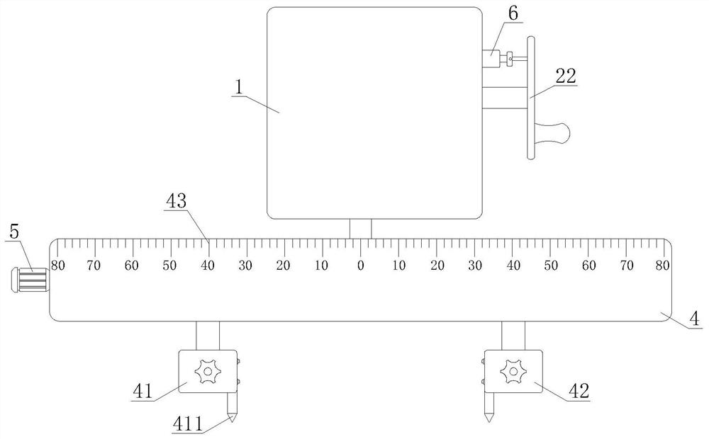
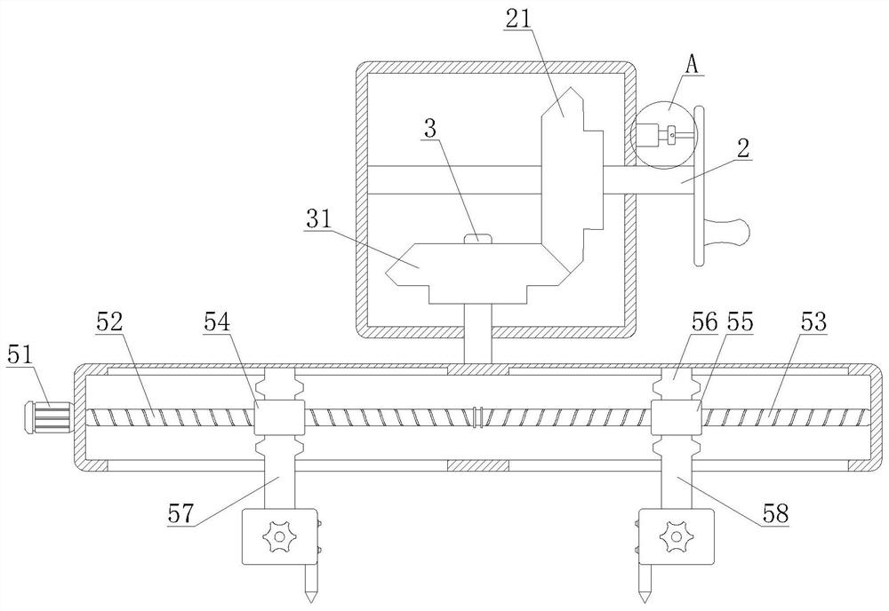
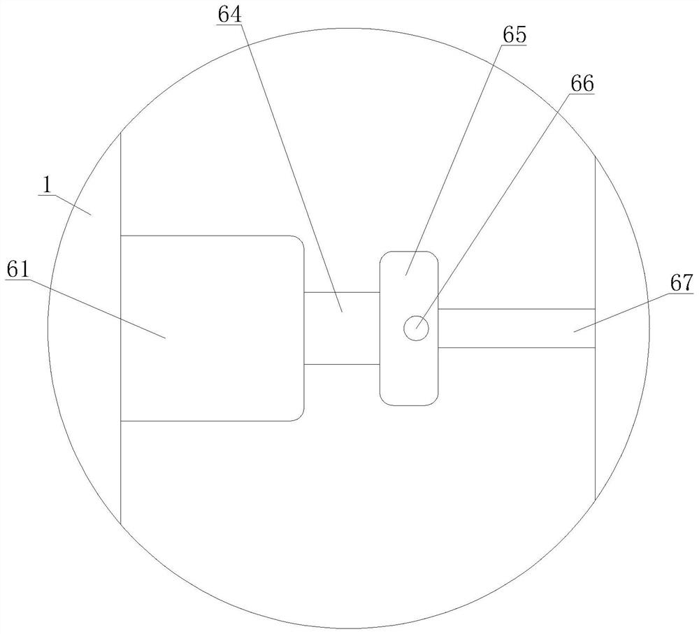
[0030] refer to figure 1 , a spiral tool adjustment mechanism for precision CNC gantry slotting machine, including a slide seat 1, a drive shaft 2 is installed on the slide seat 1, and a bevel gear A21 is installed on the drive shaft 2 through a spline, and the bevel gear A21 meshes with the bevel gear B31 , the bevel gear B31 is mounted on the transmission shaft 3 through a spline, the transmission shaft 3 is movably connected to the sliding seat 1 through th...


PUM


Abstract

The invention discloses a spiral tool setting mechanism and method for a precise numerical control gantry grooving machine, and belongs to the technical field of precise numerical control gantry grooving machines. The spiral tool setting mechanism for the precise numerical control gantry grooving machine comprises a sliding seat, wherein a drive shaft is arranged on the sliding seat; a bevel gearA is arranged on the drive shaft and meshes with a bevel gear B; the bevel gear B is arranged on a transmission shaft; one end of the transmission shaft penetrates through the sliding seat and is connected with a fixed seat; and a tool apron A and a tool apron B are arranged on the fixed seat and are arranged on the fixed seat through a drive mechanism. According to the spiral tool setting mechanism and method for the precise numerical control gantry grooving machine provided by the invention, a handle drives the tool apron A and the tool apron B to adjust a grooving angle, so that the universality is high; the handle can be fixed onto the sliding seat through a fixing mechanism, so that grooving tools can be fully guaranteed to groove smoothly; and the space between the tool apron A and the tool apron B can be adjusted through the drive mechanism, and the grooving tools arranged on the tool apron A and the tool apron B can be used for grooving at the same time, so that two notches canbe formed at a single time, and the grooving efficiency is greatly improved.

Description

technical field [0001] The invention relates to the technical field of precision numerical control gantry slotting machines, in particular to a spiral knife adjustment mechanism and method for precision numerical control gantry slotting machines. Background technique [0002] The door frame, also known as the door frame, is generally composed of two vertical frames and an upper frame. When the door has a bright part, there is also a middle horizontal frame. There are also middle mullions for multi-leaf doors. The door frame is the link between the door leaf, the transom and the wall. Due to its high strength and long service life, the aluminum alloy door frame is more and more favored by consumers and the market. In recent years, the scope of use Therefore, it is imminent to improve the production efficiency of door frames. [0003] Aluminum alloy door frames are generally bent from sheet metal. Before bending, a precision CNC gantry slotting machine is usually used to remo...

Claims


Application Information

Patent Timeline
Patent Type & Authority Applications(China)
IPC IPC(8): B23Q15/22B23Q15/26B23Q17/22
CPCB23Q15/22B23Q15/26B23Q17/22
Inventor 张玉陈麒
Owner 安徽鑫威亚机械制造股份有限公司
Learn More