Wooden walking stick automatic scorching equipment capable of achieving safety
A safe and wooden technology, applied in the field of automatic burning equipment for wooden crutches, can solve the problems of time-consuming, labor-intensive, low efficiency, low safety of hand-held spray guns, uneven heating on the surface of wooden crutches, etc., and achieve the effect of uniform heating
- Summary
- Abstract
- Description
- Claims
- Application Information
AI Technical Summary
Problems solved by technology
Method used
Image

Examples
Embodiment 1
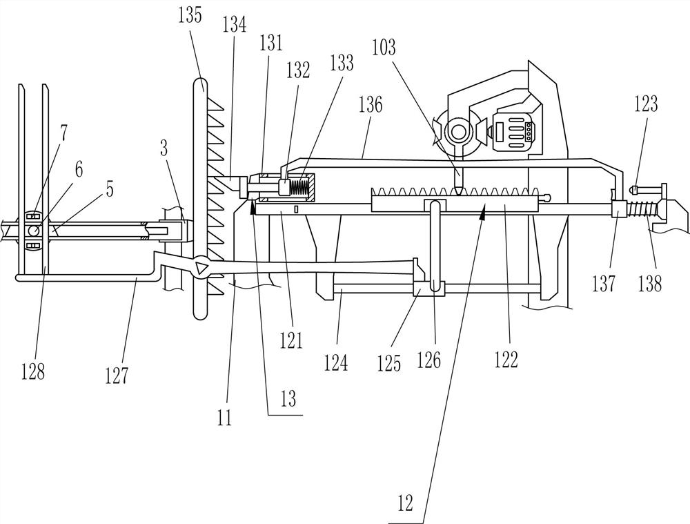
[0024] A safe wooden crutch automatic burning device, such as figure 1 As shown, it includes base plate 1, first guide rail 2, first guide sleeve 3, first slide rail 4, first slider 5, contact rod 6, heater 7, clamping device 8, support frame 9, driving device 10. Fixed seat 11, translation device 12 and intermittent lowering device 13, two sets of first guide rails 2 are connected to the left side of the bottom plate 1, and first guide sleeves 3 are slidingly connected to the first guide rails 2, so A first slide rail 4 is connected between the front sides of the first guide sleeve 3, a first slide block 5 is slidably connected inside the first slide rail 4, and a contact rod 6 is connected to the front side of the first slide block 5. , a heater 7 is connected to the rear side of the first slider 5, a clamping device 8 is provided between the upper and lower sides of the first guide rail 2, the heater 7 is located on the front side of the clamping device 8, and the bottom pl...
Embodiment 2
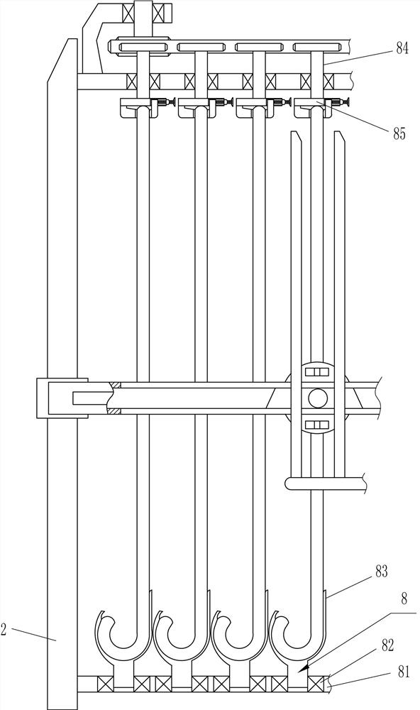
[0027] On the basis of Example 1, such as Figure 2-5 As shown, the clamping device 8 includes a connecting plate 81, a first bearing seat 82, a rotating frame 83, a first rotating rod 84, a connecting block 85, a clip 86, a movable piece 88 and a fastening screw 89, which are installed The relationship is:
[0028] The upper and lower sides of the first guide rail 2 are connected with a connecting plate 81, and a plurality of groups of first bearing seats 82 are evenly distributed in the connecting plate 81, and a rotating frame 83 is connected in the first bearing seat 82 on the lower side. A first rotating rod 84 is connected inside the first bearing seat 82 on the upper side, and the position of the first rotating rod 84 corresponds to the rotating frame 83, and the lower side of the first rotating rod 84 is connected with a connecting block 85. The left side of the lower side of the connecting block 85 is connected with clips 86, the right side of the connecting block 85...
Embodiment 3
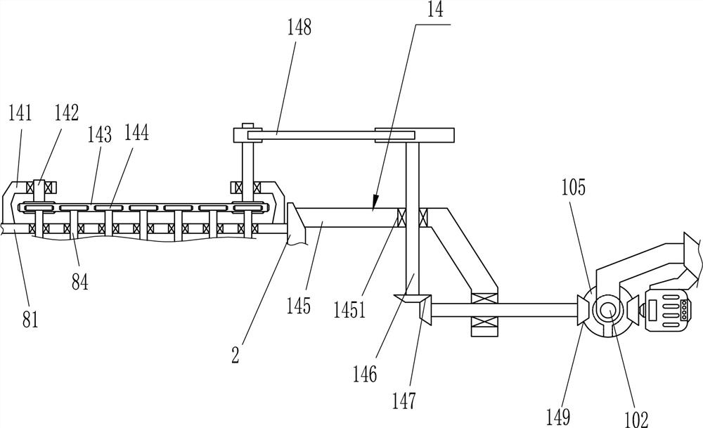
[0040] On the basis of Example 2, such as Figure 6 As shown, a transmission device 14 is also included. The transmission device 14 is provided on the upper side of the first rotating rod 84. The transmission device 14 includes a second bearing seat 141, a second rotating rod 142, and a first belt transmission assembly 143. , circular gear 144, connecting frame 145, the third bearing seat 1451, the third rotating rod 146, the second gear transmission assembly 147, the second belt transmission assembly 148 and the third gear transmission assembly 149, the installation relationship is:
[0041] The upper left and right sides of the upper connecting plate 81 are connected with second bearing housings 141, the second bearing housings 141 are connected with second rotating rods 142, and the lower sides of the second rotating rods 142 are connected with The first belt transmission assembly 143, the upper side of the first rotating rod 84 is connected with a circular gear 144, the ci...
PUM
 Abstract
Description
Claims
Application Information