Floating garbage intercepting and clearing device and clearing method for water engineering
A technology for water conservancy projects and cleaning equipment, applied in water conservancy projects, cleaning of open water surfaces, construction, etc., can solve problems such as inability to adjust, inconvenient garbage cleaning, and small garbage cleaning range, so as to increase the collection range and increase the amount of cleaning Effect
- Summary
- Abstract
- Description
- Claims
- Application Information
AI Technical Summary
Problems solved by technology
Method used
Image

Examples
Embodiment 1
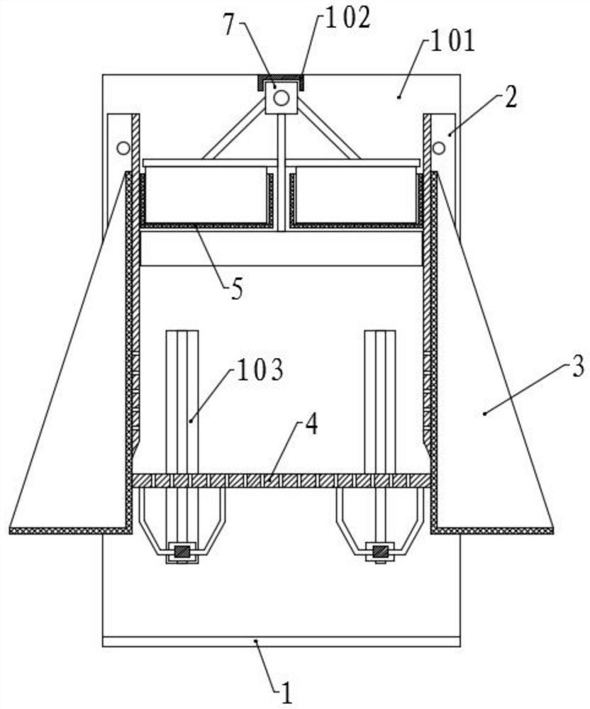
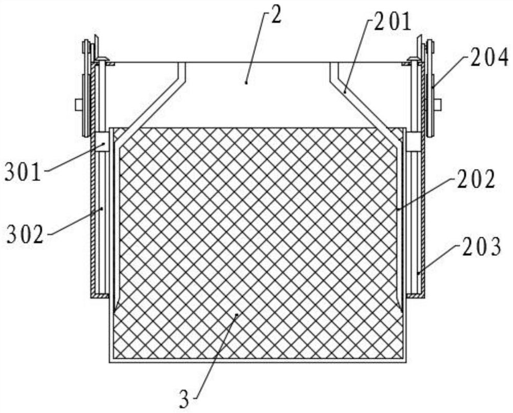
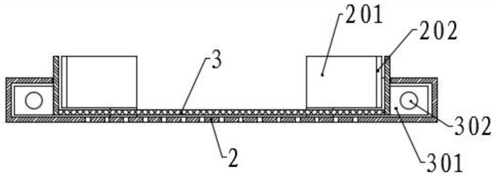
[0050] Please refer to the accompanying drawings, the present invention provides a technical solution: a floating garbage interception and cleaning device for water conservancy projects, including a base 1 arranged at the bottom of the waterway, side plates 101 are symmetrically fixed on both sides of the top surface of the base 1, and the two side plates There is a lifting mechanism between the lower parts of 101, two parallel fixed mesh grooves 5 are symmetrically fixed between the upper parts, and a moving groove 102 is fixed between the top parts, and a scraping mechanism is arranged at the moving groove 102, and one of the side plates 101 The position corresponding to the fixed mesh groove 5 and the scraping mechanism is provided with a discharge port, and the outer sides of the two fixed mesh grooves 5 are provided with a collecting mechanism, and the collecting mechanism is correspondingly connected with the side plates 101 on both sides;
[0051] The collection mechanis...
Embodiment 2
[0064] The structure of this embodiment is basically the same as that of Embodiment 1, the difference is that a collection chamber 107 is provided at the position corresponding to the discharge port on the side plate 101, and a pulverization chamber 108 is connected to the bottom of the collection chamber 107, and in the pulverization chamber 108 A crushing mechanism is provided, the bottom of the collection chamber 107 is set in a bucket shape, and the lowest part of the bottom surface is provided with a first outlet, and communicates with the crushing chamber 108 through the first outlet, and the bottom of the crushing chamber 108 is inclined, and the lower end is provided with a The second outlet, the crushing mechanism includes two symmetrical and parallel crushing rollers 10, the crushing rollers 10 are rotatably connected to the side wall of the crushing chamber 108, and one end is fixed with a crushing gear 1001, the two crushing gears 1001 mesh with each other, and one o...
Embodiment 3
[0067] The structure of this embodiment is basically the same as that of Embodiment 2, the difference is that an L-shaped transmission chamber 106 is provided above the collection chamber 107, and the lower part of the transmission chamber 106 is located on one side of the crushing chamber 108, and the crushing gear 1001 is located on the transmission chamber 108. The lower part of the cavity 106, one end of the third screw rod 701 extends into the upper part of the transmission cavity 106, and a third transmission assembly is arranged between the crushing gear 1001 and the third screw rod 701, and the third transmission assembly includes one of the crushing gears 1001 The sixth bevel gear fixed coaxially, the sixth bevel gear meshes with the fifth bevel gear 1002, and the center of the fifth bevel gear 1002 is fixed with the first transmission shaft 1003, the first transmission shaft 1003 and the side wall of the transmission chamber 106 Rotation connection, and the top is fix...
PUM
 Abstract
Description
Claims
Application Information
 - R&D
- Intellectual Property
- Life Sciences
- Materials
- Tech Scout
- Unparalleled Data Quality
- Higher Quality Content
- 60% Fewer Hallucinations
Browse by: Latest US Patents, China's latest patents, Technical Efficacy Thesaurus, Application Domain, Technology Topic, Popular Technical Reports.
© 2025 PatSnap. All rights reserved.Legal|Privacy policy|Modern Slavery Act Transparency Statement|Sitemap|About US| Contact US: help@patsnap.com