Waste collection device of shaping machine

A technology of waste collection and planer, which is applied in the direction of planer/slotting machine, router, maintenance and safety accessories, etc. It can solve the problems of reducing the efficiency of waste transportation, affecting the efficiency of waste treatment, and affecting the efficiency of waste collection, so as to improve the follow-up Effects of processing efficiency, reducing occupied volume, and increasing collection range

Pending Publication Date: 2018-09-28
朱志勇
View PDF11 Cites 4 Cited by
  • Summary
  • Abstract
  • Description
  • Claims
  • Application Information

AI Technical Summary

Problems solved by technology

[0002] Bullhead planer is a kind of planer that makes linear reciprocating motion. The ram has a planer. It is named because the tool holder at the front end of the ram is shaped like a bull's head. The bullhead planer is mainly used for small and medium-sized bullhead planers. Therefore, the moving speed of the ram is uneven, and waste will be generated during the processing, so it is necessary to use the planer waste collection device, and the factory staff usually park the collection device next to these waste materials, and then use some Small tools move these waste materials to the collection device, which wastes time and labor. At the same time, the collection cart generally cannot follow the worktable to move left and right, which affects the collection efficiency of waste materials, and the waste generated when the planer is working Most of them are irregular, which not only require a large space for storage, but also easily hurt the people who pass by them. At the same time, because most of the waste is fluffy, the efficiency of transporting these wastes will be reduced, and the cleaning personnel will have to run several times to remove them all. Thereby affecting the efficiency of waste material follow-up treatment, therefore, the present invention proposes a kind of planer waste material collection device to solve the problems existing in the prior art

Method used


Image

  • Waste collection device of shaping machine
  • Waste collection device of shaping machine
  • Waste collection device of shaping machine

Examples


Embodiment Construction

[0016] In order to deepen the understanding of the present invention, the present invention will be further described below in conjunction with the examples, which are only used to explain the present invention, and do not constitute a limitation to the protection scope of the present invention.

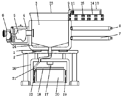
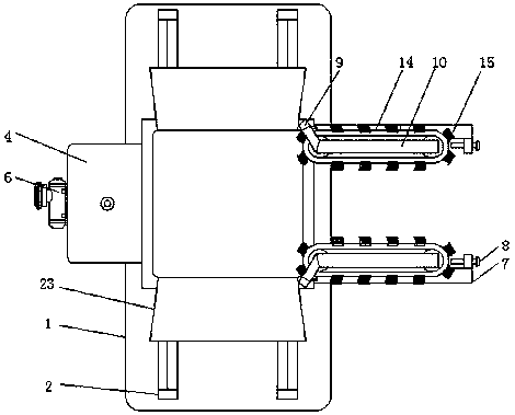
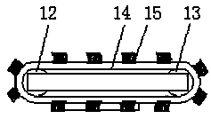
[0017] according to figure 1 , 2 , 3, the present embodiment provides a planer waste collection device, comprising a mounting plate 1, both sides of the top of the mounting plate 1 are provided with chute 2, the chute 2 is provided with a slide block A collection bin 3, a dust collection bin 4 is provided on one side of the collection bin 3, and a dust collection bag 5 is arranged inside the dust collection bin 4, and the opening of the dust collection bag 5 communicates with the collection bin 3 through a suction port, The air suction port is provided with a separating gauze, and an air pump 6 is installed on the side of the dust collection bin 4 away from the collection bin 3, and...


PUM

PropertyMeasurementUnit
lengthaaaaaaaaaa

Abstract

The invention discloses a waste collection device of a shaping machine. The device comprises a mounting plate, sliding grooves are formed in the two sides of the top of the mounting plate, collectionbins are arranged on the sliding grooves through sliding blocks, dust collection bins are arranged on one sides of the collection bins, dust collection bags are arranged in the dust collection bins, and openings of the dust collection bags communicate with the collection bins through exhaust suction openings. Through cooperation of a driving roller, a driven roller, a belt and a cleaning brush, waste on a table board of a worktable can be collected into the collection bins, the collection device is provided with a hinge rod and a bolt, the collection bins and the work table board are fixed together, in cooperation with the sliding grooves, the collection bins can move left and right along with the worktable, the waste can be conveniently collected, meanwhile, baffles are arranged on the tops of the collection bins in an inclined manner, the waste collection range can be widened, the waste can be prevented from falling on the surrounding of the device, the collection device combines collection and compression forming, and the waste subsequent treatment efficiency is improved.

Description

technical field [0001] The invention relates to the field of mechanical processing, in particular to a planer waste collecting device. Background technique [0002] Bullhead planer is a kind of planer that makes linear reciprocating motion. The ram has a planer. It is named because the tool holder at the front end of the ram is shaped like a bull's head. The bullhead planer is mainly used for small and medium-sized bullhead planers. Therefore, the moving speed of the ram is uneven, and waste will be generated during the processing, so it is necessary to use the planer waste collection device, and the factory staff usually park the collection device next to these waste materials, and then use some Small tools move these waste materials to the collection device, which wastes time and labor. At the same time, the collection cart generally cannot follow the worktable to move left and right, which affects the collection efficiency of waste materials, and the waste generated when ...

Claims


Application Information

Patent Timeline
Patent Type & Authority Applications(China)
IPC IPC(8): B23D7/00B23Q11/00
CPCB23D7/00B23Q11/0042
Inventor 朱志勇
Owner 朱志勇
Why Eureka
Try Eureka