
Scrap iron removal equipment

A technology for cleaning equipment and iron filings, which is applied in the direction of metal processing equipment, metal processing machinery parts, maintenance and safety accessories, etc., and can solve problems such as laborious cleaning of debris, inability to clean debris quickly, large and long debris, etc. , to achieve the effects of convenient operation, reduced impact, and simple device structure

Active Publication Date: 2019-08-30
南京贝斯特金属材料有限公司
View PDF8 Cites 4 Cited by
  • Summary
  • Abstract
  • Description
  • Claims
  • Application Information

AI Technical Summary

Problems solved by technology

[0004] Although the above-mentioned patents can quickly clean up debris, it is more laborious to clean up larger pieces of debris, and when lathes process metal, they often produce larger and longer debris, which cannot be quickly removed. to clean up

Method used


Image

  • Scrap iron removal equipment
  • Scrap iron removal equipment
  • Scrap iron removal equipment

Examples


Embodiment Construction

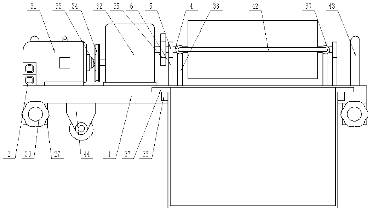
[0024] The present invention is specifically described below in conjunction with accompanying drawing, as Figure 1-6 As shown, in this implementation:

[0025] In this device, the device is powered by connecting with an external power supply, and the external power supply is electrically connected with the drive motor 31 for power supply. 31 is electrically connected, so as to control the operation of the device.

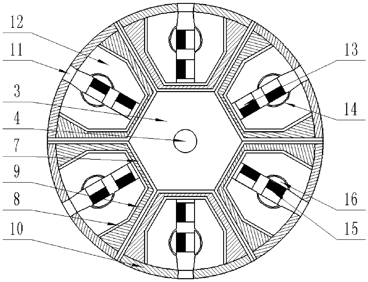
[0026] The invention of the present application lies in the structural design of the rotating chip cleaning device, combined with the attached figure 1 , attached figure 2 , attached image 3 And attached Figure 4 , the rotating chip cleaning device includes a regular hexagonal drum 3 at one end above the base 1, a rotating shaft 4 is installed in the regular hexagonal drum 3, two rotating bearings 5 ​​are installed at both ends of the rotating shaft 4, and the rotating bearing 5 is connected to the base 1 is connected by a rotating bearing seat 6, a trapezo...


PUM


Abstract

The invention discloses scrap iron removal equipment. The scrap iron removal equipment comprises a base, wherein a fixing device is arranged below the base; a driving device is arranged above the base; a scrap iron collecting box device is arranged on one side of the base; a control switch is arranged at the upper end of the base; and a rotary scrap iron removal device is arranged above the base.Through the matching of a first permanent magnet and a second permanent magnet, and through the rotation of a rotating shaft and the matching of an adjusting baffle and a large arc baffle, the scrap ion is collected and removed; after the scrap iron is produced in machining, an orthohexagonal rotating cylinder sucks the scrap iron while rotating, and large and small scrap iron can be collected simultaneously, so that the collection range of the equipment is improved; meanwhile, the equipment is simple in structure and convenient to operate; the scrap iron can be effectively collected, and theinfluence of the scrap on metal processing is reduced; and the equipment has the advantages of simple operation and high practicability.

Description

technical field [0001] The invention relates to the field of equipment related to machining and cleaning, in particular to equipment for cleaning scrap iron. Background technique [0002] As people have higher and higher precision requirements for parts and metal processing, they rely more and more on lathe processing. More and more metal debris accumulates on the lathe, which not only affects the quality of metal processing, but also easily scratches the skin of the operator. [0003] In the patent CN201410630998.3 - a debris cleaning device for metal processing lathes, a groove chamber is provided on the lathe bed, and the metal debris is sent to the negative pressure generator through the suction cup provided at the bottom of the groove chamber , the steel cylinder sends the gas inside it to the negative pressure generator, a high-speed airflow is formed in the negative pressure generator, the air extraction device is activated, and the gas in the tube hole and debris cl...

Claims


Application Information

Patent Timeline
Patent Type & Authority Applications(China)
IPC IPC(8): B23Q11/00
CPCB23Q11/0042B23Q11/0064
Inventor 宋延升
Owner 南京贝斯特金属材料有限公司
Learn More