
Steel pipe stand column positioning device and positioning construction method thereof

A technology of positioning device and steel pipe column, which is applied in the direction of foundation structure engineering, building, sheet pile wall, etc., and can solve the problems of high cost of HPE pipe inserting machine, difficulty in anchoring and positioning of uplift piles, and difficulty in displacement during hole construction , to achieve the effect of simple, convenient and easy-to-operate adjustment method, intuitive and visible adjustment effect, and saving equipment cost

Inactive Publication Date: 2020-09-18
CHINA POWER CONSTR SOUTHERN CONSTR INVESTMENT CO LTD +2
View PDF8 Cites 1 Cited by
  • Summary
  • Abstract
  • Description
  • Claims
  • Application Information

AI Technical Summary

Problems solved by technology

[0003] When carrying out the cover-excavation method, it is necessary to arrange steel pipe columns. Due to the high positioning accuracy of the cover-excavation steel pipe columns, it is difficult to anchor the uplift piles at the lower part of the steel pipe columns, and the construction method has certain difficulties.
At present, the construction of steel pipe columns in cover and excavation stations in China has gradually adopted the HPE insertion machine method to replace the initial manual downhole positioning method. However, due to the high cost of the HPE insertion machine, the large area occupied by the supporting equipment, and the difficulty in moving the hole during construction, it is harmful to the construction site. Certain requirements, in the case of a narrow site and a large number of steel pipe columns, the adaptability of this positioning construction method is not high

Method used


Image

  • Steel pipe stand column positioning device and positioning construction method thereof
  • Steel pipe stand column positioning device and positioning construction method thereof
  • Steel pipe stand column positioning device and positioning construction method thereof

Examples


Embodiment Construction

[0036] In order to make the technical problems, technical solutions and beneficial effects to be solved by the present invention clearer, the present invention will be further described in detail below in conjunction with the accompanying drawings and embodiments. It should be understood that the specific embodiments described here are only used to explain the present invention, not to limit the present invention.

[0037] It should be noted that when a component is referred to as “fixing” or “setting” or “connecting” another component, it may be directly or indirectly located on the other component. The terms "upper", "lower", "left", "right", "front", "rear", "horizontal", "top", "bottom", "inner", "outer", etc. indicate orientation or position The orientation or position shown in the drawings is only for convenience of description, and should not be construed as a limitation on the technical solution. "Plurality" means two or more, unless otherwise clearly and specifically...


PUM


Abstract

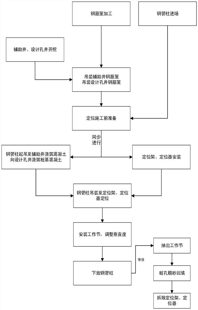
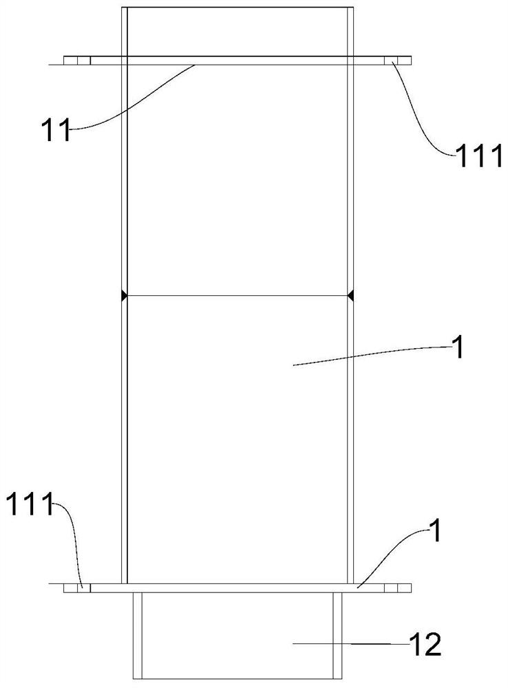
The invention discloses a steel pipe stand column positioning device and a positioning construction method thereof. The steel pipe stand column positioning device comprises a positioning frame and a working section, wherein a steel pipe column penetrates through a stand column hole of the positioning frame to enter a designed hole well, the working section is connected with the steel pipe column,an adjusting device on the positioning frame adjusts the perpendicularity of the steel pipe column through the working section, the steel pipe column is positioned by using the positioning frame and apositioner, and the perpendicularity of the steel pipe column is adjusted by the working section and a telescopic oil cylinder. According to the steel pipe stand column positioning device and the positioning construction method thereof, accurate positioning of the steel pipe column in a narrow construction site is realized, the positioning precision is high, stable and controllable, deviation iseasy to correct, the operation method is simple and convenient, the technical difficulty is low, tool equipment can be recycled, the cost is low, the economic benefit is obvious, super concrete capable of keeping plasticity for a long time is newly arranged, the problems that the steel pipe column is inserted into a pile foundation to be resisted, and pile pulling is difficult are solved, the steel pipe column construction method is changed into a positioning frame rear-inserting method, concrete pouring is carried out on the interior of the steel pipe column in advance, the positioning frameis subjected to line production, the construction efficiency is improved, and the construction progress is accelerated.

Description

technical field [0001] The invention relates to the technical field of engineering construction, and more specifically, relates to a steel pipe column positioning device and a positioning construction method thereof. Background technique [0002] The subway project is an important municipal transportation project in a modern city, and it carries the important task of urban residents with a large passenger flow. During the construction of the subway, due to the large excavation area of ​​the subway station, the shallow covering soil, and the surrounding buildings are too close together, in order to prevent the subsidence of the adjacent buildings caused by the excavation of the foundation pit as much as possible, or to restore the road traffic as soon as possible, However, there is a lack of a fixed covering structure, and the cover-excavation method is often used for construction. [0003] When the cover-excavation method is carried out, steel pipe columns need to be arrang...

Claims


Application Information

Patent Timeline
IPC IPC(8): E02D5/38E02D13/04E02D15/04
CPCE02D5/38E02D13/04E02D15/04
Inventor 段景川席小青吴晓斌贺荣流王明明闫黎明刘尚旭
Owner CHINA POWER CONSTR SOUTHERN CONSTR INVESTMENT CO LTD
Learn More