Water intake structure

A technology for structures and pump houses, which is applied to buildings, water supply devices, drinking water devices, etc., can solve the problems of high project cost, high requirements for the construction site and excavation range, and unsuitability, and achieve low requirements for the construction site and save energy. To build the effect of materials and simple structure

Active Publication Date: 2019-02-05
CHINA ENERGY ENG GRP GUANGDONG ELECTRIC POWER DESIGN INST CO LTD
View PDF3 Cites 1 Cited by
  • Summary
  • Abstract
  • Description
  • Claims
  • Application Information

AI Technical Summary

Problems solved by technology

attached figure 1 It is a reinforced concrete box culvert connection method. When constructing the water diversion box culvert, a reinforced concrete retaining wall needs to be set up to prevent the open channel waves from crossing the box culvert and entering the forebay of the pump room. Therefore, the construction cost of the connection section of this scheme is very high; figure 2 It is a reinforced concrete buttress retaining wall connection method. This scheme requires a large area of ​​the reinforced concrete buttress retaining wall, so it has high requirements for the construction site and excavation range, and is not suitable for use in projects with tight sites. Moreover, the reinforced concrete Buttress retaining walls are also expensive

Method used


Image

  • Water intake structure
  • Water intake structure
  • Water intake structure

Examples


Embodiment Construction

[0027] Embodiments of the present invention are described in detail below:

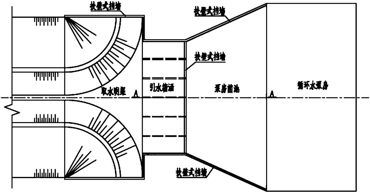
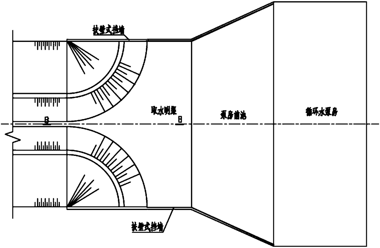
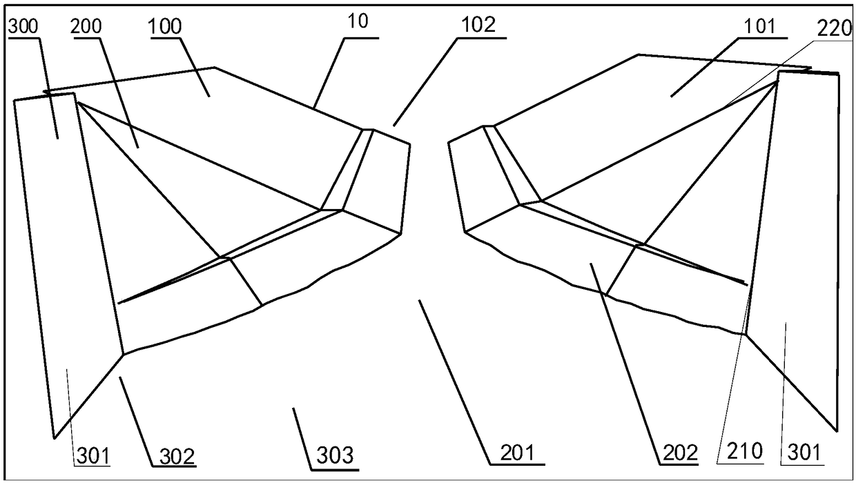
[0028] Such as figure 1 and figure 2 As shown, the water intake structure 10 includes an open water intake channel 100, a pump room forebay 300, and a transition section 200; the open water intake channel 100 includes two opposite slopes 101, and the two side slopes define a water intake channel 102, and water is drawn from the water intake channel Enter the pump room forebay 300, the pump room forebay 300 includes two oppositely arranged side walls 301, and the two side walls 301 define and form the water inlet 302 of the pump room forebay 300; figure 1 As shown, there are two transition sections 200, the two transition sections 200 are respectively connected between the two side slopes 101 and the two side walls 301, and the two transition sections 200 are defined to communicate between the water intake channel 102 and the water inlet 302 The transition channel 201. Such as figure 1 , 2 As sho...


PUM


Abstract

The invention relates to a water intake structure of coastal thermal power plants. The water intake structure comprises a water intake open channel, a pump house fore bay and transition sections; thewater intake open channel comprises two slopes oppositely arranged, and the two slopes are defined to form a water intake channel; the pump house fore bay comprises two side walls oppositely arranged,and the two side walls are defined to form a water inlet of the pump house fore bay; the two transition sections are connected between the two slopes and the two side walls respectively, and the twotransition sections are defined to form a transition channel communicated between the water intake channel and the water inlet; each transition section comprises a first connecting end connected withthe corresponding side wall, a second connecting end connected with the corresponding slope and a transition surface, and the transition surface is connected between the first connecting and the second connecting end, and is a hook face facing the transition channel. The water intake structure is low in cost, and can be applied to construction plants with a small space.

Description

technical field [0001] The invention relates to a water intake structure of a coastal power plant, and belongs to the technical field of the structure of the water intake structure of a power plant. Background technique [0002] In coastal thermal power plants, the circulating cooling water system of the unit usually adopts the secondary circulation method, which requires water to be diverted from the sea to the forebay of the circulating water pump room through an open water intake channel. The water intake open channel generally adopts an inverted trapezoidal section, while the forebay of the circulating water pump house generally adopts a rectangular section, so the connection between the two requires a transition section, a transition section from an inverted trapezoidal section to a rectangular section. [0003] In the previous coastal thermal power plant projects, the transition section of the water intake structure is mainly divided into two types, one is to connect t...

Claims


Application Information

Patent Timeline
Patent Type & Authority Applications(China)
IPC IPC(8): E03B3/04
CPCE03B3/04
Inventor 黄文贺马兆荣何小华彭明祥钟香兰刘晋超刘东华马旻
Owner CHINA ENERGY ENG GRP GUANGDONG ELECTRIC POWER DESIGN INST CO LTD
Why Eureka
Try Eureka