Heat exchange drying device

A heat exchange device and thermal drying technology, applied in the direction of drying gas arrangement, drying solid materials, drying chamber/container, etc., can solve the problems of energy waste, large compressor load, etc., to reduce energy waste, reduce temperature difference, and improve efficiency high effect

Active Publication Date: 2020-09-18
山东东工新能源科技有限公司
View PDF6 Cites 1 Cited by
  • Summary
  • Abstract
  • Description
  • Claims
  • Application Information

AI Technical Summary

Problems solved by technology

However, this solution uses the compressor to directly perform heating or cooling operations on

Method used


Image

  • Heat exchange drying device
  • Heat exchange drying device
  • Heat exchange drying device

Examples


Embodiment Construction

[0032]In order to enable those skilled in the art to better understand the technical solutions in the present invention, the technical solutions in the embodiments of the present invention will be clearly and completely described below in conjunction with the drawings in the embodiments of the present invention. Obviously, the described The embodiments are only some of the embodiments of the present invention, not all of them. Based on the embodiments of the present invention, all other embodiments obtained by persons of ordinary skill in the art without making creative efforts shall fall within the protection scope of the present invention.

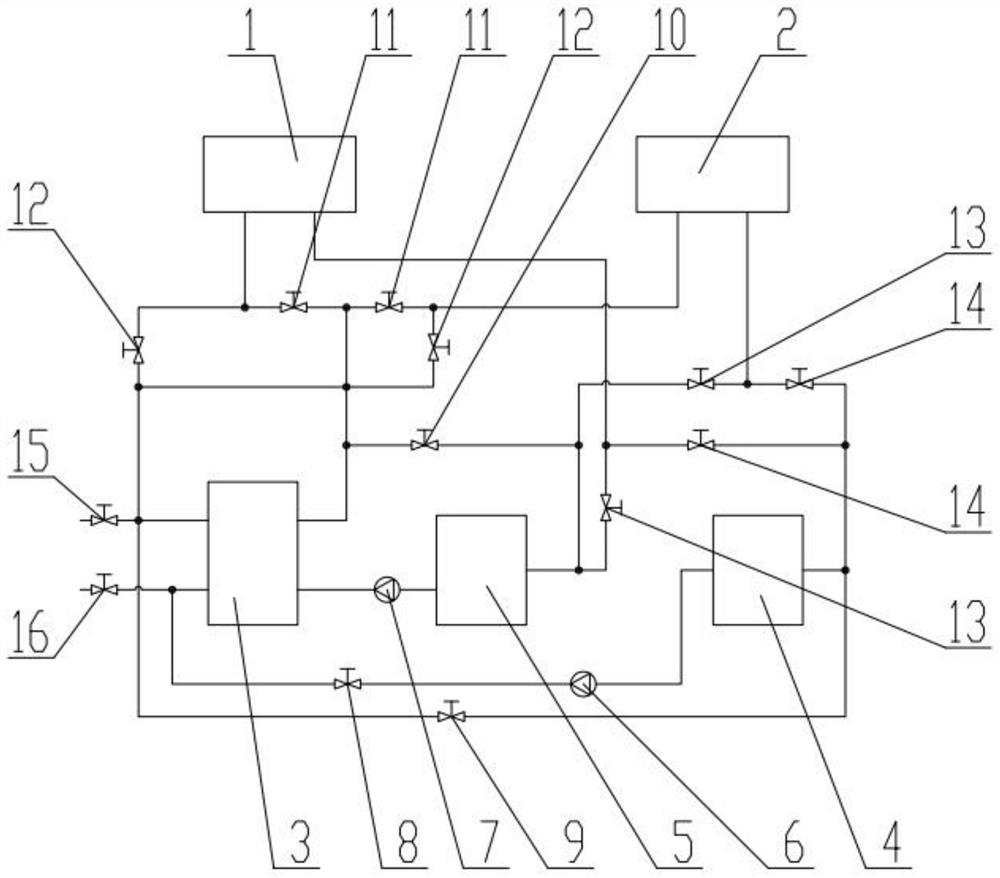
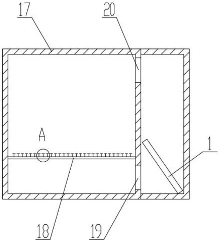
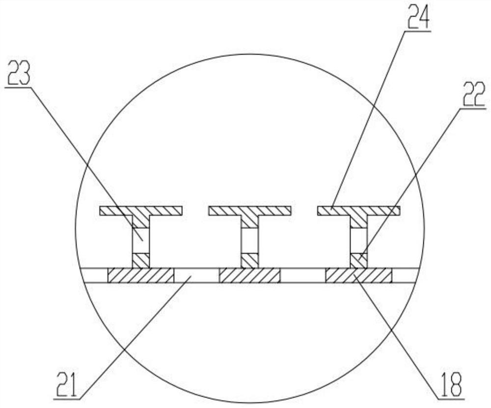
[0033] Such as Figure 1 ~ Figure 3 As shown, a heat exchange drying device is provided in this embodiment, including a drying chamber 17 and a heat exchange device, the drying chamber is provided with a drying heat exchanger, the heat exchange device is connected to the drying heat exchanger, and the heat exchange device includes a heat...


PUM


Abstract

The invention relates to the field of drying equipment, in particular to a heat exchange drying device. Heating drying and dehumidification functions can be achieved at the same time, and energy can be saved. The heat exchange drying device comprises a drying chamber and a heat exchange device. The drying chamber is provided with a drying heat exchanger. The heat exchange device is connected withthe drying heat exchanger and comprises a heat exchange unit and a cold and hot switching device. The cold and hot switching device is arranged between the heat exchange unit and a drying heat exchanger. The heat exchange unit can use a compressor unit, and refrigeration and heating are conducted simultaneously. Working states of the drying heat exchanger can be changed directly through the cold and hot switching device. Products can be dried through the heating mode. The refrigeration mode can be used for dehumidification.

Description

technical field [0001] The invention relates to the field of drying equipment, in particular to a heat exchange drying device. Background technique [0002] In the prior art, common drying equipment uses high-temperature air to accelerate the evaporation of water in the product to achieve drying, but the humidity in the air after drying is extremely high, and it is necessary to collect the water in the air in time, otherwise it will be re- Back to the product, affecting the drying effect of the product. During the drying process, it is necessary to set up a dehumidification device to collect and discharge the water vapor in the air. The additional dehumidification device increases the manufacturing cost of the equipment. In addition, since the moisture content in the air changes during the drying process, it is difficult to control the working conditions of the dehumidification equipment, resulting in increased energy consumption. [0003] Patent No. 201520673372.0 Chinese...

Claims


Application Information

Patent Timeline
IPC IPC(8): F26B9/06F26B21/00F26B21/04F26B21/08F26B25/00F26B25/18
CPCF26B9/066F26B21/002F26B21/004F26B21/04F26B21/086F26B25/005F26B25/18
Inventor 李守涛
Owner 山东东工新能源科技有限公司
Why Eureka
Try Eureka