Hole site measuring device

A technology for hole position measurement and measurement components, which is applied to measurement devices, mechanical measurement devices, and mechanical devices, etc., can solve problems such as errors, low detection efficiency, and difficult positioning, and achieve convenient maintenance, fewer device failures, and convenient measurement data. Effect

Pending Publication Date: 2020-09-18
成都齐友科技有限公司
View PDF0 Cites 0 Cited by
  • Summary
  • Abstract
  • Description
  • Claims
  • Application Information

AI Technical Summary

Problems solved by technology

[0003] Caliper detection method: the inspector uses a caliper to measure the hole position. This detection method is labor-intensive and the detection efficiency is low.
[0004] Altimeter detection method: inspectors use an altimeter to measure the hole position. This detection method is labor-intensive and low-efficiency
[0005] Three-coordinate detection method: Inspectors use three-coordinates to measure the hole position. The investment cost of three-coordinate equipment is relatively large, and this detection method takes too long time in three coordinates, and other products will be waiting for inspection.
[0008] 1. The existing mainstream detection is still a vernier caliper, manual positioning, manual data reading, human influence factors are large, positioning is difficult, and there will be certain errors
[0009] 2. The existing detection tools are difficult to accurately and systematically measure the specific data of the hole position offset. Basically, it can only be used to judge whether the hole position has offset, the offset direction, etc., and there is no way to measure the hole position. Bits are digitized for precise records

Method used


Image

  • Hole site measuring device
  • Hole site measuring device
  • Hole site measuring device

Examples


Embodiment 1

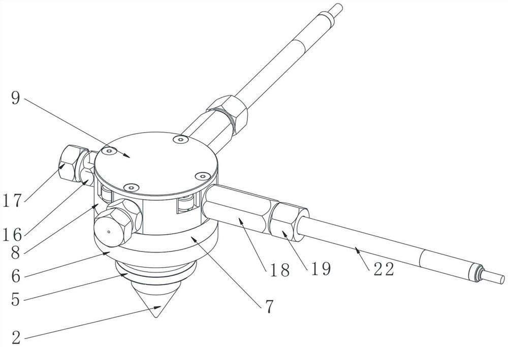
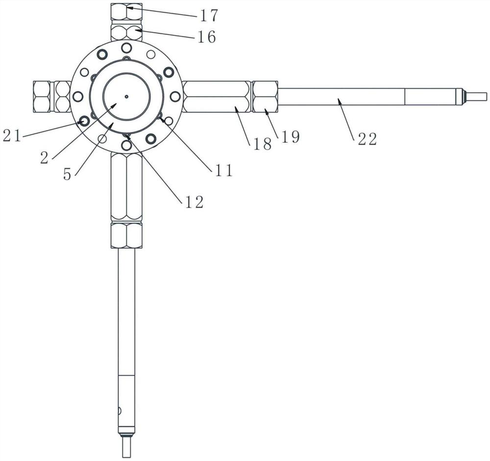
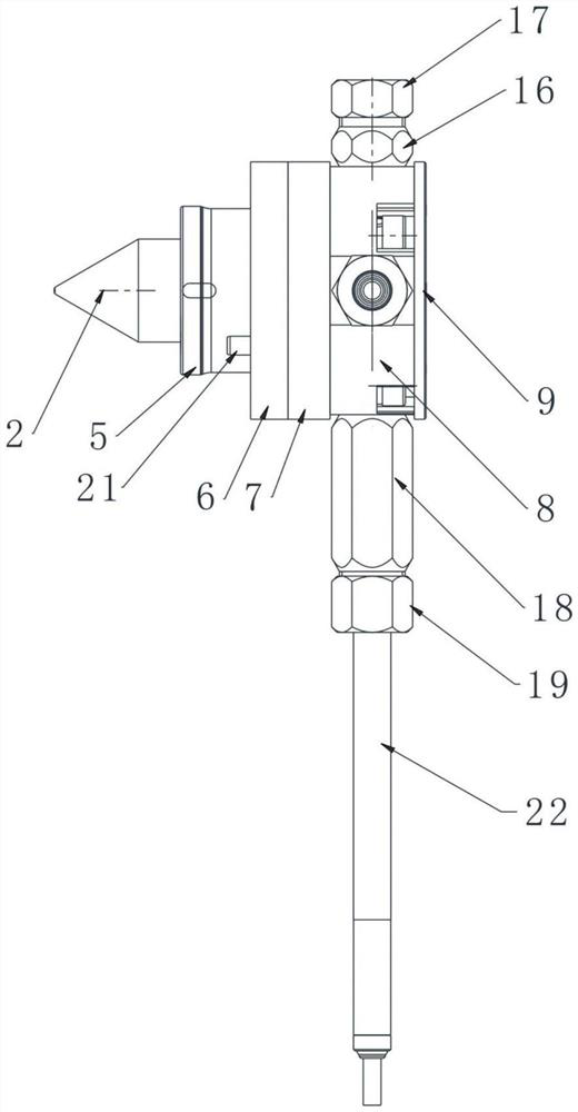
[0037] like figure 1 figure 2 image 3 Figure 4 Figure 5 As shown, a hole position measuring device includes a guide column 1, a measuring head 2, a zero alignment ring 5, a front fixing ring 6, a middle fixing ring 7, a rear fixing ring 8 and a measuring assembly, and the measuring assembly includes a measuring The rod and the dial indicator, the dial indicator probe is in contact with the end of the measuring rod, and the middle part of the guide column 1 is provided with a disc; the lower end of the guide column 1 is equipped with the probe 2, and the upper end surface of the probe 2 is connected to the front fixing ring 6 The lower end surface is in contact, the middle fixing ring 7 is installed on the front fixing ring 6, the disc in the middle of the guide column 1 is located inside the middle fixing ring 7, the rear fixing ring 8 is installed on the middle fixing ring 7, and surrounds the side of the rear fixing ring 8 Set up the measuring assembly, the measuring...

Embodiment 2

[0048] This embodiment is on the basis of embodiment 1, the measurement component is improved to form the second form of the measurement component, the specific design adopted is to use the distance sensor to realize electronization, and the measurement component cancels the dial gauge 22 and related percentages Table installation components, such as guide sleeve 18, lock nut 19, lock sleeve 20, and a distance sensor and signal sending device are added at the rear end of the probe 2. The design of this measurement component can directly obtain the measurement results and send the results to The upper computer can realize faster measurement, and eliminate the unfavorable factors such as errors and mistakes caused by manual reading of data.


PUM


Abstract

The invention discloses a hole site measuring device. The device comprises a guide post, a measuring head, a zero setting ring, a front end fixing ring, a middle fixing ring and a rear end fixing ring, a measuring head is arranged below the guide column; the upper end face of the probe contacts with the lower end face of the front-end fixing ring. A middle fixing ring is mounted on the front end fixing ring; a disc in the middle of the guide column is located in the middle fixing ring. A rear end fixing ring is mounted on the middle fixing ring; a measuring assembly is arranged around the sideface of the rear end fixing ring, a measuring rod of the measuring assembly makes contact with the top of the guide column, the front end fixing ring and the measuring head are sleeved with the zerosetting ring, and the measuring assembly can be arranged in two modes of being externally connected with a dial indicator and internally provided with a sensor and can be used for accurately and rapidly measuring the position of a hole.

Description

technical field [0001] The invention belongs to the technical field of hole position measurement, and in particular relates to a hole position measurement device. Background technique [0002] The detection of holes is a very common detection data in the industrial production process. There are mainly three existing detection methods: [0003] Caliper detection method: The inspector uses a caliper to measure the hole position. This detection method is labor-intensive and the detection efficiency is low. [0004] Altimeter detection method: inspectors use an altimeter to measure the hole position. This detection method is labor-intensive and low in detection efficiency. [0005] Three-coordinate detection method: Inspectors use three-coordinates to measure the hole position. The investment cost of three-coordinate equipment is relatively large, and this detection method takes too long time in three coordinates, and other products will be waiting for inspection. [0006] Wit...

Claims


Application Information

Patent Timeline
Patent Type & Authority Applications(China)
IPC IPC(8): G01B5/00G01B21/00
CPCG01B5/00G01B21/00
Inventor 蔡启新
Owner 成都齐友科技有限公司
Why Eureka
Try Eureka