Mold parts inspection process
A technology for testing stations and testing tools, which is applied in angle/taper measurement and other directions, and can solve problems such as error, low detection efficiency of mold parts, and complicated detection steps
- Summary
- Abstract
- Description
- Claims
- Application Information
AI Technical Summary
Problems solved by technology
Method used
Image

Examples
Embodiment 1
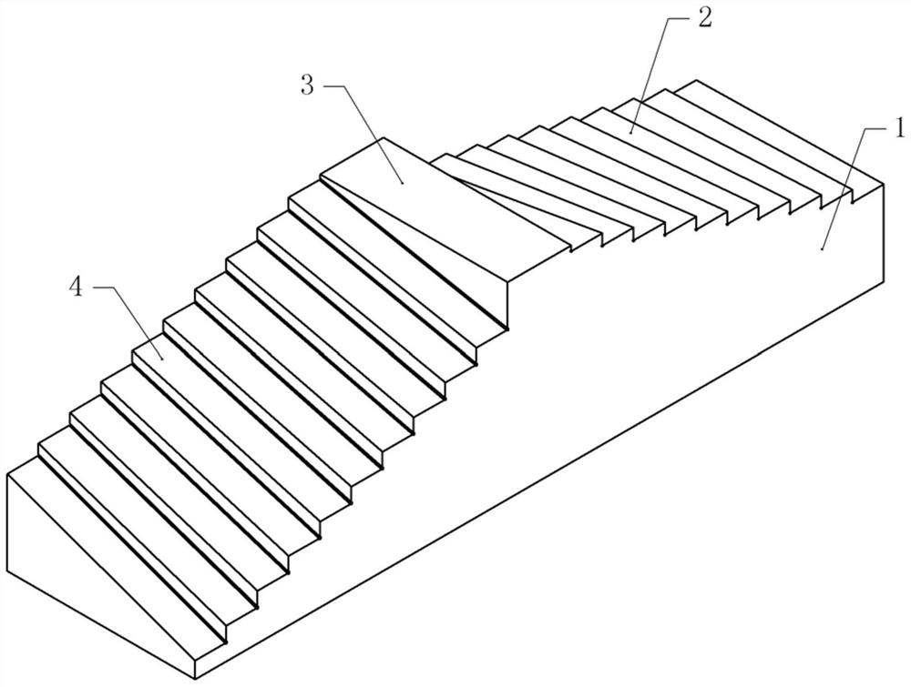
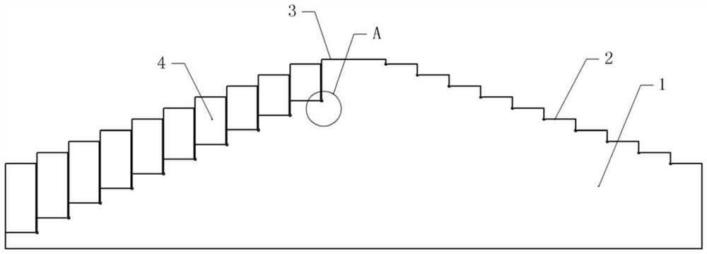
[0041] Basic as attached figure 1 , attached figure 2 And attached Figure 4 As shown, the mold parts inspection process,
[0042] S1: Prepare the detection tool, the detection tool includes the boss 1, there are several inclined detection stations on both sides of the boss 1, the detection station on the side of the boss 1 is inclined towards the front of the boss 1, the other The detection station on one side is inclined towards the back of the boss 1 . The inclination angles of the detection stations gradually increase from top to bottom, and the inclination angles of two adjacent detection stations differ by 1°. In this embodiment, there are ten detection stations on each side of the boss 1, the inclination angle of the top detection station is 1°, and the inclination angle of the bottom detection station is 10°, that is, the inclination angle of the detection station is 1°. The tilt angle distribution is: 1°, 2°, 3°, 4°, 5°, 6°, 7°, 8°, 9°, 10°.
[0043] combined wi...
Embodiment 2
[0048] The difference between embodiment two and embodiment one is that, as attached Image 6 As shown, the main piece 411 and the secondary piece 412 are horizontally slidably connected in the avoidance groove 41, and the cross-sections of the main piece 411 and the secondary piece 412 are arc-shaped, and when the main piece 411 and the secondary piece 412 are fitted together, they can also form a Arc-shaped, the main sheet 411 and the secondary sheet 412 are bonded with elastic gaskets, and the elastic gaskets are made of rubber.
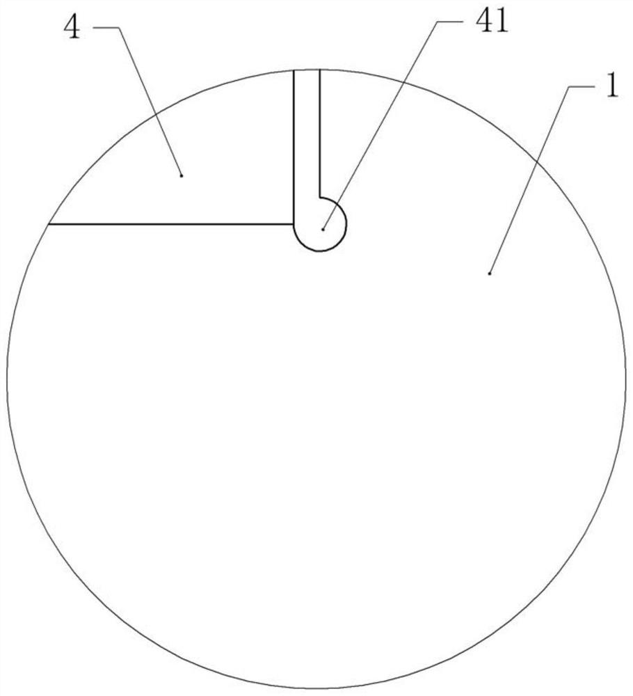
[0049] In S3 , the angled side of the mold part to be inspected faces the inclined surface of the inspection station, and the corners of the mold part are inserted into the avoidance groove 41 .
[0050] When the thickness of the edges and corners of the mold part is B / C / D (B>C>D), when D is encountered, the elastic gasket can be deformed to a certain extent to adapt to the D thickness.
[0051] When encountering condition C, the operator takes out...
Embodiment 3
[0055] The difference between embodiment three and embodiment one is that, as attached Figure 7 And attached Figure 8 As shown, in S1, several baffles 5 are arranged on both sides of the boss 1, and the baffles 5 are located at the lower side of the detection station, and the height of the baffles 5 gradually increases with the height of the detection station. Figure 9 As shown, the baffle plate 5 includes an outer plate 51 and an inner plate 55, the inner plate 55 is located in the outer plate 51, the inner plate 55 is welded with a protrusion, the outer plate 51 is provided with a chute vertically slidingly connected with the protrusion, and the outer plate 51 is vertically slidably connected with the protrusion. A channel 53 is opened on the plate 51 , and an air hole 54 facing the escape groove 41 is communicated with the channel 53 , and a pressure relief valve 52 is fixed in the channel 53 by screws. The bottom of the outer plate 51 is rotatably connected with a holl...
PUM
 Abstract
Description
Claims
Application Information
 - R&D Engineer
- R&D Manager
- IP Professional
- Industry Leading Data Capabilities
- Powerful AI technology
- Patent DNA Extraction
Browse by: Latest US Patents, China's latest patents, Technical Efficacy Thesaurus, Application Domain, Technology Topic.
© 2024 PatSnap. All rights reserved.Legal|Privacy policy|Modern Slavery Act Transparency Statement|Sitemap