Backlight module, liquid crystal display device and electronic equipment
A liquid crystal display device and backlight module technology, which is applied in optics, nonlinear optics, instruments, etc., can solve the problems of poor Mini-LED uniformity, backlight uniformity, and increased backlight weight, and achieve high light efficiency, high light efficiency and high light efficiency. Uniformity, cost reduction effect
- Summary
- Abstract
- Description
- Claims
- Application Information
AI Technical Summary
Problems solved by technology
Method used
Image

Examples
Embodiment 1
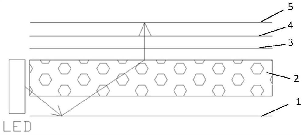
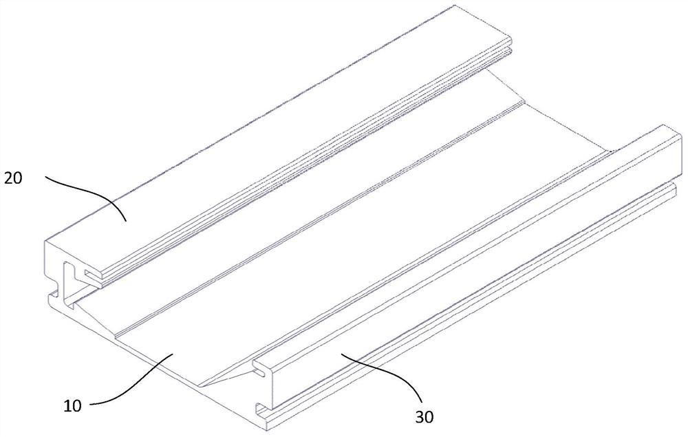
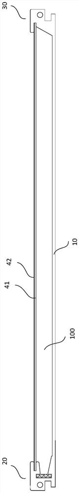
[0041] This embodiment provides a backlight module, according to Figure 2-5 As shown, the backlight module includes: a backplane 10; a light source part 20 disposed on one side of the backplane, and the light source part 20 has an LED light source; and a reflection part 302 disposed on the other side of the backplane 10 opposite to the light source part 20 On one side, the reflective portion 30 has a reflective surface 32 , and at least part of the surface of the reflective surface 32 is inclined relative to the back plate.
[0042] A hollow light guide structure 100 is formed between the light source part 20 and the reflection part 30 . No light guide plate is provided between the light source part 20 and the reflection part 30, and the hollow light guide structure 100 is filled with gas, such as air or other gases, or a vacuum. Other gases are inert gases. Those skilled in the art should understand that the hollow light guide structure 100 here does not mean that there is...
Embodiment 2
[0064] This embodiment provides a backlight module, the backlight module includes: a backplane 10; a light source part 20, disposed on one side of the backplane, the light source part 20 has an LED light source; and a reflector 302, disposed on the backplane 10 , on the other side opposite to the light source portion 20 , the reflective portion 30 has a reflective surface 32 .
[0065] according to Figure 6A , The difference from Embodiment 1 is that the reflective surface 32 in this embodiment adopts a different configuration. The reflective surface 32 has multiple reflective surfaces, and the reflective surface 32 can be a continuous multiple reflective surface, or a discontinuous multiple reflective surface separately provided.
[0066] Preferably, the reflective surface 32 is a multi-segment continuous reflective surface, preferably, the angle between at least one segment of the reflective surface and the back plate is different from that of other segments of the reflect...
Embodiment 3
[0071] This embodiment provides a backlight module, the backlight module includes: a backplane 10; a light source part 20, disposed on one side of the backplane, the light source part 20 has an LED light source; and a reflector 302, disposed on the backplane 10 , on the other side opposite to the light source portion 20 , the reflective portion 30 has a reflective surface 32 .
[0072] according to Figure 6B , the difference from Embodiment 2 is that the reflective surface 32 in this embodiment adopts a different configuration. The reflective surface 32 is a multi-segment continuous reflective surface, preferably, the angle between at least one segment of the reflective surface and the back plate is different from that of other segments of the reflective surface. And at least one section of the reflective surface is perpendicular to the back plate.
[0073] Preferably, each section of reflective surface is a strip reflective surface 321, 322, 324 arranged parallel to the ba...
PUM
 Abstract
Description
Claims
Application Information
 - R&D
- Intellectual Property
- Life Sciences
- Materials
- Tech Scout
- Unparalleled Data Quality
- Higher Quality Content
- 60% Fewer Hallucinations
Browse by: Latest US Patents, China's latest patents, Technical Efficacy Thesaurus, Application Domain, Technology Topic, Popular Technical Reports.
© 2025 PatSnap. All rights reserved.Legal|Privacy policy|Modern Slavery Act Transparency Statement|Sitemap|About US| Contact US: help@patsnap.com