A lower leg mechanism and a biped robot equipped with the lower leg mechanism

A calf and ankle technology, applied in the field of biped robots, can solve the problems of large swing inertia, difficult control, heavy weight, etc., and achieve the effect of improving load carrying capacity, easy to be controlled, and high rigidity

Active Publication Date: 2021-03-19
敬科(深圳)机器人科技有限公司
View PDF6 Cites 0 Cited by
  • Summary
  • Abstract
  • Description
  • Claims
  • Application Information

AI Technical Summary

Problems solved by technology

[0003] In order to better model human walking, the lower leg of the biped robot, especially the ankle, requires light weight, small size, and excellent rigidity. Existing biped robots are equipped with a large number of connecting components and drive components at the ankle connection position, resulting in The ankle position of the robot is heavy, so when the calf swings around the knee joint, the swing inertia is large and difficult to control

Method used


Image

  • A lower leg mechanism and a biped robot equipped with the lower leg mechanism
  • A lower leg mechanism and a biped robot equipped with the lower leg mechanism
  • A lower leg mechanism and a biped robot equipped with the lower leg mechanism

Examples


Embodiment 1

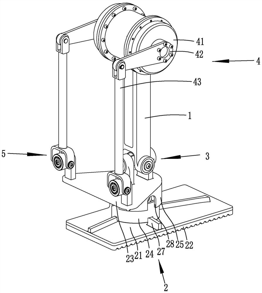
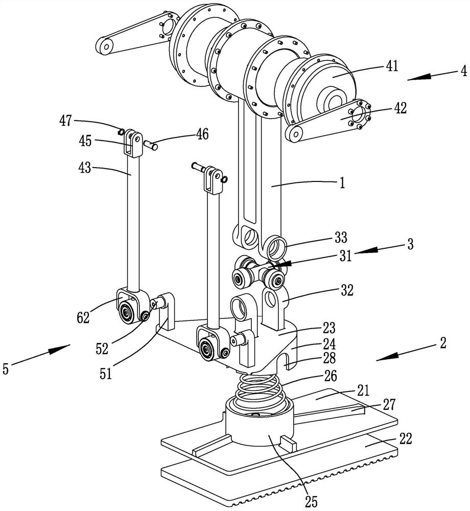
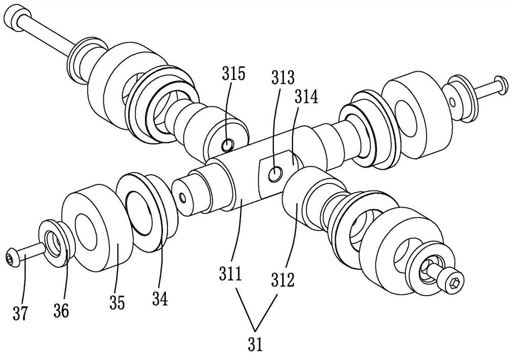
[0041] refer to figure 1 , this embodiment discloses a calf mechanism, including a calf frame 1, an integrated foot 2, an ankle support assembly 3 and two sets of ankle drive assemblies 4. The calf frame 1 and the integrated foot 2 are universally articulated through the above-mentioned ankle support assembly 3, and the ankle The drive assembly 4 is used to drive the integrated foot 2 to rotate around the ankle support assembly 3 .

[0042] refer to figure 2 , the integrated foot 2 has good shock absorption capability and can adapt to complex terrain. It includes a sole 21, a shock pad 22 bonded to the underside of the sole 21, and a support seat 23 arranged above the sole 21. The upper middle of the sole 21 A first connecting cylinder 24 is welded, and a second connecting cylinder 25 is welded on the lower side of the support base 23 . A shock-absorbing spring 26 is also arranged in the first connecting cylinder 24. One end of the shock-absorbing spring 26 is fixedly conne...

Embodiment 2

[0056] This embodiment discloses a biped robot, including the lower leg mechanism in the first embodiment.


PUM


Abstract

The invention relates to a shank mechanism. The shank mechanism comprises a shank framework and an integrated foot, and further comprises an ankle supporting assembly and two ankle driving assemblies.The shank framework and the integrated foot are universally hinged through the ankle supporting assembly. Each ankle driving assembly comprises a rotary driving part installed on one side of the upper end of the shank framework, an output rod fixedly connected to an output shaft of the rotary driving part and a connecting rod hinged to the end, away from the rotary driving part, of the output rod, and the connecting rod is universally hinged to the upper side of the integrated foot; and the rotary driving parts in the two ankle driving assemblies are symmetrically arranged on the two sides ofthe shank framework respectively. The shank mechanism has the following advantages: the rotary driving parts are arranged at the upper ends of the shank framework, and then the action of the rotary driving parts is transmitted to the integrated foot through the output rod and the connecting rod, so that the weight of the ankle is reduced, the mass center of the shank is raised, and shank movementis easier to control.

Description

technical field [0001] The invention relates to the field of bipedal robots, in particular to a calf mechanism and a bipedal robot equipped with the calf mechanism. Background technique [0002] A bipedal robot is a bionic type of robot that can walk upright, has a good degree of freedom, and is flexible, free and stable. As a mechanically controlled dynamic system, bipedal robots contain rich dynamic properties. In the future production and life, humanoid biped walking robots can help humans solve many problems, such as a series of dangerous or heavy tasks such as carrying objects and emergency rescue. [0003] In order to better model human walking, biped robots are required to be light in weight, small in size, and excellent in rigidity below the calf, especially at the ankle. Existing biped robots are provided with a large number of connection components and drive components at the ankle connection position, resulting in The weight of the robot's ankle position is larg...

Claims


Application Information

Patent Timeline
Patent Type & Authority Patents(China)
IPC IPC(8): B62D57/032
CPCB62D57/032
Inventor 郭廷山孙敬颋王恒恒陈杰
Owner 敬科(深圳)机器人科技有限公司
Why Eureka
Try Eureka