Rotary optical module and projection device

A technology for optical modules and projection devices, which is applied to optics, projection devices, optical components, etc., can solve the problems of small outer diameter of metal rings, large vibration of component bodies, and low utility of copper sheets, so as to avoid structural instability and improve reliability. Operability and the effect of reducing the vibration phenomenon

Active Publication Date: 2021-08-06
CORETRONIC
View PDF3 Cites 0 Cited by
  • Summary
  • Abstract
  • Description
  • Claims
  • Application Information

AI Technical Summary

Problems solved by technology

However, the current metal ring is located on the side of the turntable farther away from the motor (that is, the smooth side), so when the balance is completed, the center of mass of the rotor must fall in the turntable
In this way, it will cause a large axial force, which will eventually lead to a large vibration of the component body
In addition, the existing metal ring has only one axial turning retaining wall, so the curing glue and copper sheet can only be added at the outer diameter near the retaining wall, and the outer diameter of the metal ring is small, and the copper sheet can only be placed on the opposite side of the turntable. Inner ring part
When performing dynamic balancing, it takes more time, and copper sheets of the same quality are less effective
In addition, known optical elements such as reflective glass or light-transmitting glass have a small bonding area with the metal ring, so the structural strength is not good
When rotating at high speed, if there is an external force vibrating at the natural frequency of the structure, resonance will occur, causing serious deformation of the turntable, and finally making the body vibrate and noise loud

Method used


Image

  • Rotary optical module and projection device
  • Rotary optical module and projection device
  • Rotary optical module and projection device

Examples


Embodiment Construction

[0017] The aforementioned and other technical contents, features and effects of the present invention will be clearly presented in the following detailed description of a preferred embodiment with reference to the accompanying drawings. The directional terms mentioned in the following embodiments, such as: up, down, left, right, front or back, etc., are only referring to the directions of the drawings. Accordingly, the directional terms are used to illustrate and not to limit the invention.

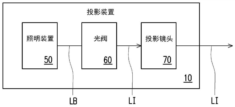
[0018] figure 1 It is a schematic diagram of a projection device according to an embodiment of the present invention. Please refer to figure 1 . This embodiment provides a projection device 10 including an illumination system 50 , at least one light valve 60 and a projection lens 70 . Wherein, the lighting system 50 is used for providing the lighting beam LB. At least one light valve 60 is disposed on the transmission path of the illumination beam LB for converting the illumination b...


PUM


Abstract

A rotary optical module includes a driving element, a turntable, an optical material, a balance ring, and a first counterweight material. The driving element is provided with a body and a rotating shaft body extending from the body. The turntable is sleeved on the rotating shaft body and is provided with a first surface and a second surface which are opposite. The optical material is disposed on the first surface of the turntable. The balance ring is arranged between the driving element and the turntable and is provided with a third surface and a fourth surface which are opposite to each other, and the third surface and the second surface face each other. The first counterweight material is disposed on the fourth surface of the balance ring. The balance ring is provided with an outer retaining wall protruding from the fourth face and at least one inner retaining wall, and the first counterweight material abuts between the outer retaining wall and the at least one inner retaining wall. The invention further provides a projection device comprising the rotary optical module. According to the rotary optical module and the projection device provided by the invention, the mass center position of the rotary optical module can be effectively reduced, the deformation of the turntable caused by an unstable structure is avoided, and the vibration phenomenon during rotation is reduced.

Description

technical field [0001] The present invention relates to an optical module and an electronic device, and in particular to a rotating optical module and a projection device. Background technique [0002] The projection device is a display device for producing large-scale images, and has been continuously improving with the evolution and innovation of technology. The imaging principle of the projection device is to convert the illumination beam generated by the lighting system into an image beam through a light valve, and then project the image beam to a projection target (such as a screen or a wall) through a projection lens to form a projection image. [0003] In the lighting system, the current cost-effective way to generate red and green light is to use a blue laser diode to send an excitation beam to the fluorescent color wheel, and use the excitation beam to excite the phosphors of the fluorescent color wheel to generate yellow-green light. Then, the required red light o...

Claims


Application Information

Patent Timeline
Patent Type & Authority Applications(China)
IPC IPC(8): G02B26/00G03B21/20
CPCG02B26/00G03B21/20H04N9/3158G03B21/2033G03B21/204G03B21/16G02B26/008H04N9/3111
Inventor 蔡佳伦谢启堂
Owner CORETRONIC
Why Eureka
Try Eureka