Cam rotor pump

A cam rotor pump and cam rotor technology, applied in the direction of rotary piston pumps, pumps, pump components, etc., can solve the problems of reduced energy efficiency of the device, difficulty in ensuring the tightness of the rotor and the pump body, etc.

Active Publication Date: 2020-09-22
温州市格东机械有限公司
View PDF9 Cites 0 Cited by
  • Summary
  • Abstract
  • Description
  • Claims
  • Application Information

AI Technical Summary

Problems solved by technology

[0003] Rotor lobe pumps are widely used in the field of modern pipeline transportation. However, the existing rotor lobe pumps often have the following shortcomings during use. It is often difficult to ensure that the rotor and the pump There is effective sealing between the bodies for a long time, and often there is a slight air leakage in the rotor pump, which will greatly reduce the overall energy efficiency of the device and require maintenance and replacement

Method used


Image

  • Cam rotor pump
  • Cam rotor pump
  • Cam rotor pump

Examples


Embodiment 1

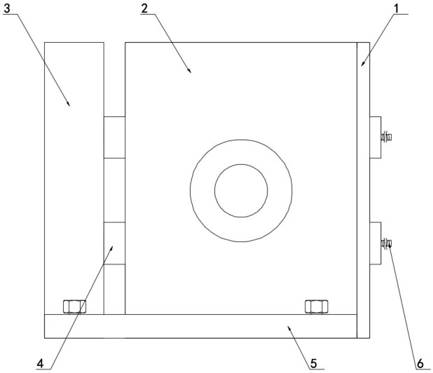
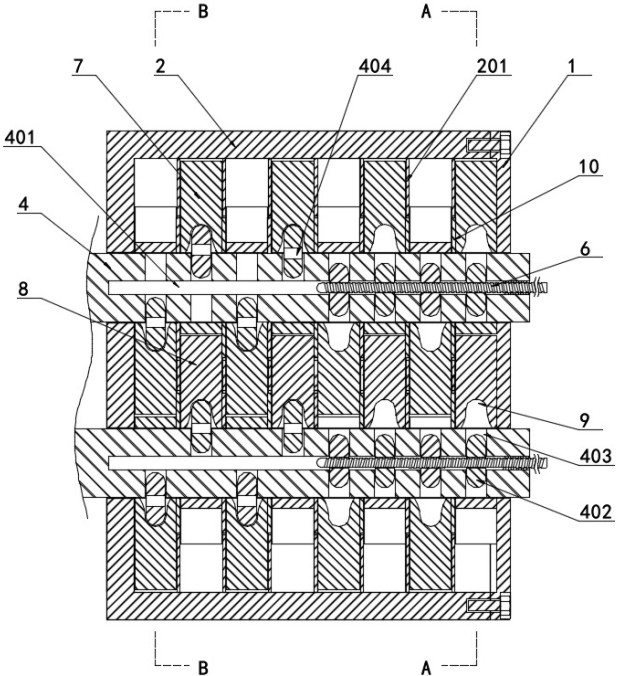
[0024] Embodiment one, with reference to Figure 1-4 , the lobe rotor pump, including a fixed base 5 and a drive mechanism 3 fixedly installed on the fixed base 5 and a pump casing 2, and also includes two transmission shafts 4 fixedly connected to the output end of the drive mechanism 3, and the inner cavity of the pump casing 2 is fixed with at least A spacer 201, at least one rotor mechanism is rotatably connected to the inner cavity of the pump casing 2, and the outer cover 1 is detachably installed at the opening of the pump casing 2, and the two transmission shafts 4 run through the pump casing 2 and are sleeved on the extension end of the outer cover 1. The adjusting screw 6, the rotor mechanism includes a first cam rotor 7 and a second cam rotor 8, the sides of the first cam rotor 7 and the second cam rotor 8 are fixedly connected with an isolation disc 10, and the isolation disc 10 and the isolation disc 201 have a through hole The first cam rotor 7 and the second cam...

Embodiment 2

[0025] Embodiment two, refer to Figure 1-4 , the first cam rotor 7 and the second cam rotor 8 are rotationally connected with the two transmission shafts 4 respectively, and the center of the transmission shaft 4 is provided with a shaft hole 401, and the shaft hole 401 is screwed and connected with the adjusting screw 6, and the transmission shaft 4 is radially At least one through hole 403 is opened, at least one through hole 403 is vertically connected with the shaft hole 401, at least one through hole 403 runs through the outer wall of the transmission shaft 4, at least one through hole 403 is slidingly connected with a clamping rod 402, the first The centers of the cam rotor 7 and the second cam rotor 8 are provided with a card slot 9, the card slot 9 is engaged with the card rod 402, and at least one card rod 402 is provided with a center hole 404, and the center hole 404 is in clearance fit with the adjusting screw rod 6 After the adjusting screw 6 is inserted into the...

Embodiment 3

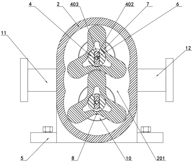
[0026] Embodiment three, refer to image 3 A water inlet pipe 11 and a water outlet pipe 12 are fixedly installed on both sides of the pump casing 2, so as to facilitate the delivery of liquid to the pump casing 2.

[0027] Working principle: firstly, through the isolation between multiple first cam rotors 7 and multiple second cam rotors 8 by multiple spacers 201, and the rotational connection between the spacer disc 10 and the through hole at the center of the spacer disc 201, the isolation The disk 10 separates multiple rotor mechanisms, so that the multiple rotor mechanisms work independently of each other, avoiding the failure of a single rotor mechanism causing the failure of the entire device; secondly, through the sliding connection between the clamping rod 402 and the through hole 403 , and the screw-in connection between the adjusting screw 6 and the shaft hole 401, so that the adjusting screw 6 is screwed into the shaft hole 401 and inserted into the center hole 404...


PUM


Abstract

The invention discloses a cam rotor pump. The cam rotor pump comprises a fixed base, a driving mechanism and a pump shell, wherein the driving mechanism and the pump shell are fixedly installed on thefixed base. The cam rotor pump further comprises two transmission shafts fixedly connected with the output end of the driving mechanism; at least one partition disc is fixedly arranged in an inner cavity of the pump shell; at least one rotor mechanism is rotationally connected to the inner cavity of the pump shell; an outer cover is detachably installed at an opening of the pump shell; and the two transmission shafts penetrate the pump shell, and the extending end of the outer cover is sleeved with an adjusting screw. In the cam rotor pump, a plurality of rotor mechanisms are adopted for isolating independent running mechanisms, the plurality of rotor mechanisms work independently, and the defect that the whole device fails due to failure of the single rotor mechanism is avoided; and theadjustable inserting rotor mechanisms are adopted, and under the condition that the output rotating speeds of the two transmission shafts are controlled to be unchanged, the overall output efficiencyof the rotor pump is effectively adjusted and used.

Description

technical field [0001] The invention belongs to the technical field of rotor pumps, in particular to a cam rotor pump. Background technique [0002] The rotor lobe pump is one of the most advanced fluid equipment in the world. Its rotor is fully rubber-coated and has strong wear resistance. The high-precision clearance fit between the rotor and the housing has strong self-priming force and high lift force. Conveying various viscous or particulate-containing media, it is suitable for various complex fluid media. The working principle of the lobe rotor pump mainly relies on two synchronous counter-rotating rotors to generate suction at the inlet during the rotation process, so as to suck in the fluid to be transported. of materials. [0003] Rotor lobe pumps are widely used in the field of modern pipeline transportation. However, the existing rotor lobe pumps often have the following shortcomings during use. It is often difficult to ensure that the rotor and the pump There i...

Claims


Application Information

Patent Timeline
Patent Type & Authority Applications(China)
IPC IPC(8): F04C2/12F04C15/00F04C15/06
CPCF04C2/126F04C2/084F04C2/086F04C15/06
Inventor 刘小波王静
Owner 温州市格东机械有限公司
Why Eureka
Try Eureka