Anti-seismic support hanger based on direction adjustment

A technology of direction adjustment and support and hanger, applied in the direction of spring/shock absorber, vibration suppression adjustment, electrical components, etc. Fixed adjustment structure and other problems to achieve the effect of improving flexibility and improving safety

Active Publication Date: 2020-09-22
安徽精工电缆桥架有限公司
View PDF9 Cites 5 Cited by
  • Summary
  • Abstract
  • Description
  • Claims
  • Application Information

AI Technical Summary

Problems solved by technology

[0004] The existing anti-seismic support and hanger based on direction adjustment has certain disadvantages in the use process. The traditional anti-seismic support and hanger based on direction adjustment does not have a rotation adjustment structure, and the traditional anti-seismic support and hanger adopts a fixed structure design, so that users The use angle of the anti-seismic support and hanger cannot be adjusted arbitrarily according to the installation angle of the cable, which reduces the flexibility of the anti-seismic support and hanger; secondly, the traditional anti-seismic support and hanger does not have a fixed adjustment structure, so that the anti-seismic support and hanger can only be installed Used in a fixed position, the anti-seismic support and hanger cannot be adjusted arbitrarily according to the installation hole position, which reduces the scope of application of the anti-seismic support and hanger; secondly, the traditional anti-seismic support and hanger does not have a combined fixed structure, so that the anti-seismic support and hanger cannot be spliced Fixed operation reduces the versatility of the anti-seismic support and hanger, and brings certain adverse effects to users

Method used


Image

  • Anti-seismic support hanger based on direction adjustment
  • Anti-seismic support hanger based on direction adjustment
  • Anti-seismic support hanger based on direction adjustment

Examples


Embodiment Construction

[0033] The technical solutions in the embodiments of the present invention will be clearly and completely described below in conjunction with the embodiments of the present invention. Apparently, the described embodiments are only some of the embodiments of the present invention, not all of them. Based on the embodiments of the present invention, all other embodiments obtained by persons of ordinary skill in the art without creative efforts fall within the protection scope of the present invention.

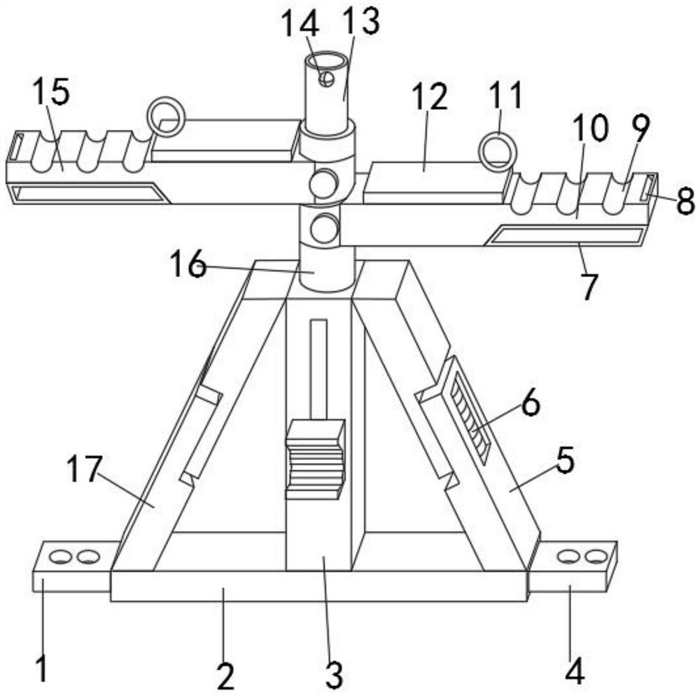
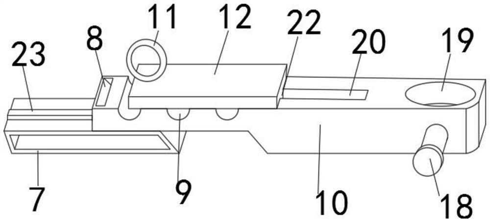
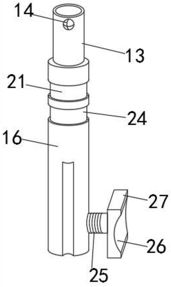
[0034] Such as Figure 1-6 As shown, a kind of anti-seismic support and hanger based on direction adjustment includes a lifting strut 16, a middle strut 3, a first bracket 10 and a second bracket 15, and the lifting strut 16 is movably socketed on the middle strut 3. Inside the upper end, the first bracket 10 is movably socketed on the upper outer surface of the lifting strut 16, and the second bracket 15 is movably installed on the outer surface of the lifting strut 16 close to t...


PUM


Abstract

The invention discloses an anti-seismic support hanger based on direction adjustment. The support hanger comprises a lifting support rod, a middle support rod, a first support and a second support, wherein the lifting support rod is movably connected with an inner side of an upper end of the middle support rod in a sleeving mode, the first support is movably connected with an outer surface of an upper portion of the lifting support rod in a sleeving mode, the second support is movably mounted on the upper part, close to the first support, of an outer surface of the lifting support rod, steering clamping grooves are formed in the inner side of the second support and the inner side of the first support in a penetrating mode, combined clamping sleeves are fixedly mounted at bottoms of the second support and the first support, sliding clamping heads are fixedly mounted in middles of outer surfaces of upper ends of the combined clamping sleeves, and the second support, the first support andthe combined clamping sleeves are fixedly connected through sliding clamping heads. The anti-seismic support hanger based on direction adjustment can perform rotation angle adjustment operation, flexibility is improved, meanwhile, the anti-seismic support hanger has a fixed adjustment structure, and the application range is widened.

Description

technical field [0001] The invention belongs to the technical field of anti-seismic support and hanger, and more specifically relates to an anti-seismic support and hanger based on direction adjustment. Background technique [0002] The anti-seismic support and hanger based on direction adjustment is a cable support and hanger for fixing cables, and multiple groups of cables can be installed and fixed by using the anti-seismic support and hanger based on direction adjustment. [0003] The comparison document CN207661221U discloses an anti-seismic support and hanger for an air duct, which is connected to the bottom surface of a building concrete structure. Beams, the heights of the two vertical beams are equal; the two ends of the first beam are respectively connected with the two vertical beams to form a U-shaped frame; the second beam is parallel to the first beam and arranged at intervals, and the two ends of the second beam are connected to each other through two connecti...

Claims


Application Information

Patent Timeline
Patent Type & Authority Applications(China)
IPC IPC(8): H02G3/04F16F15/067
CPCF16F15/067H02G3/0406H02G3/0456
Inventor 张俊俞振亚
Owner 安徽精工电缆桥架有限公司
Why Eureka
Try Eureka