Measuring device for ascertaining measurand of measurement gas

A measuring device and a technique for measuring parameters, which are applied in measuring devices, using sound waves/ultrasonic waves/infrasonic waves for material analysis, and optical means for material analysis, etc., can solve problems such as large interference, reduce interference noise, and realize length adjustment , the effect of attenuating the frequency range

Active Publication Date: 2020-09-22
AVL LIST GMBH
View PDF8 Cites 2 Cited by
  • Summary
  • Abstract
  • Description
  • Claims
  • Application Information

AI Technical Summary

Problems solved by technology

In particular, interference on the air-acoustic path through the input and output lines to the PAS measurement unit is a big problem

Method used


Image

  • Measuring device for ascertaining measurand of measurement gas
  • Measuring device for ascertaining measurand of measurement gas
  • Measuring device for ascertaining measurand of measurement gas

Examples


Embodiment Construction

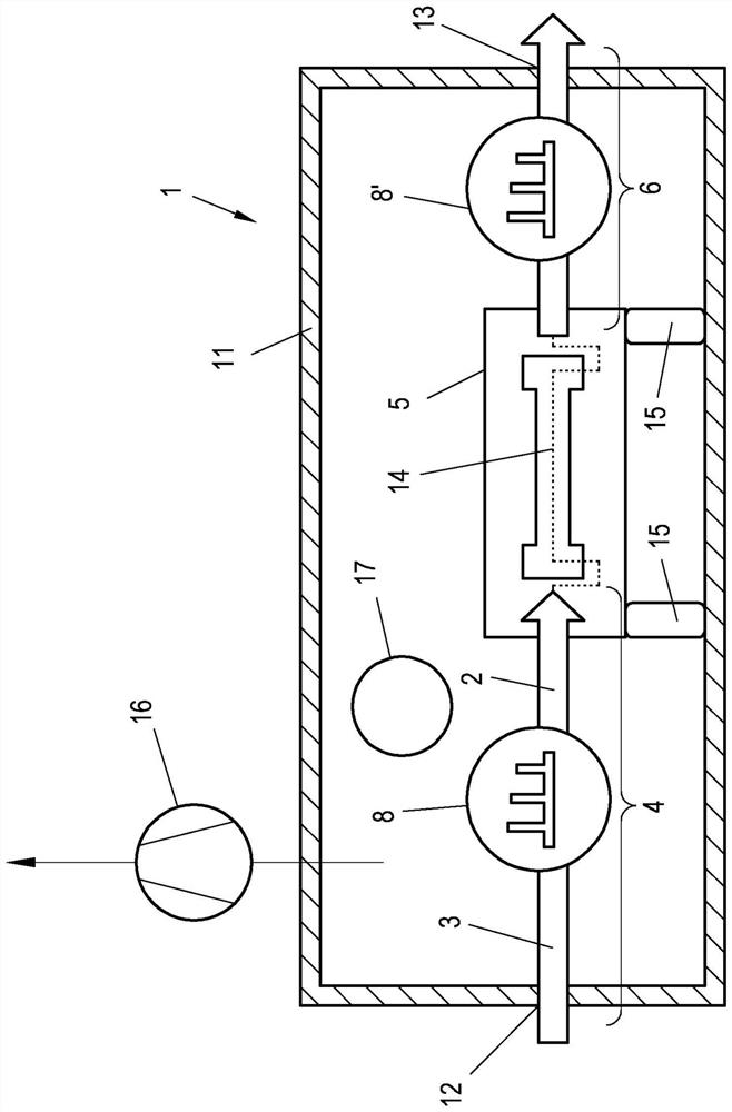
[0040] exist figure 1The main elements of the measuring device 1 are schematically shown in . The important components of the measuring device 1 are arranged in a protected manner in the housing 11 , wherein the measuring gas 2 is supplied to the measuring device 1 in the measuring gas inlet 12 and the measuring gas 2 is again in the measuring gas outlet 13 after the measurement Leave the measuring device 1. The path of the measuring gas 2 in the interior of the measuring device 1 is defined by a flow channel 3 which extends from the measuring gas inlet 12 to the measuring gas outlet. The flow channel 3 conducts the measuring gas 2 over a photoacoustic measuring cell 5 in which the measuring gas is excited with pulsed or modulated laser radiation in a known manner.

[0041] The flow channel 3 can thus be divided into three sections: the feed line 4 from the measuring gas inlet 12 to the measuring cell 5 , the flow path 14 leading through the measuring cell and defining its ...


PUM

PropertyMeasurementUnit
diameteraaaaaaaaaa

Abstract

The invention relates to a measurement device (1) for ascertaining a measure and of a measurement gas (2) by means of a photoacoustic method. The measurement device (1) has a flow channel (3) for themeasurement gas (2) with at least one supply line (4), a photoacoustic measurement cell (5), and an outlet line (6). The measurement device (1) has at least one acoustic filter element (8) coordinatedwith the fundamental frequency (18) of the measurement cell (5), which filter element comprises at least one cavity resonator (7) arranged on the flow channel (3).

Description

technical field [0001] The invention relates to a measuring device for determining a measuring parameter of a measuring gas by means of a photoacoustic method, wherein the measuring device has a flow channel for the measuring gas, the flow channel has at least one feed line, photoacoustic measuring unit and output line. [0002] Furthermore, the invention relates to a method for suppressing noise disturbances in a measuring device for ascertaining a measurement variable of a measurement gas by means of a photoacoustic method, wherein the measurement gas is guided through a flow channel which is connected in at least one The input line, the photoacoustic measuring cell and the output line are extended. Background technique [0003] Photoacoustic spectroscopy (PAS) is used very successfully for measurement methods in various fields of gas and particle measurement technology. In this case, the measurement gas (aerosol) to be examined is excited by means of an intensity-modula...

Claims


Application Information

Patent Timeline
Patent Type & Authority Applications(China)
IPC IPC(8): G01N21/17
CPCG01N21/1702G01N29/036G01N29/2418G01N29/2425G01N2021/1704G01N33/0036
Inventor H·莱因格鲁伯W·辛德勒K-C·哈姆斯T·赖尼施
Owner AVL LIST GMBH
Why Eureka
Try Eureka