
Novel machining turnover device

A technology of machining and turning device, which is applied in the field of machining, can solve the problems of inability to realize large-angle turning, inconvenient machining of workpieces, and easy slippage of workpieces, and achieves stable fixation, easy machining, and enhanced clamping strength. Effect

Active Publication Date: 2020-09-25
惠安县钗新汽车配件中心
View PDF4 Cites 2 Cited by
  • Summary
  • Abstract
  • Description
  • Claims
  • Application Information

AI Technical Summary

Problems solved by technology

[0006] Aiming at the deficiencies of the prior art, the present invention provides a new type of overturning device for mechanical processing, which overcomes the deficiencies of the prior art, has a simple structural design, and effectively solves the problem of clamping and fixing the workpiece only by two splints. Its fixing strength is low, which causes the workpiece to slip easily during the processing, and its turning angle is limited, and it cannot be turned over at a large angle, which is inconvenient for the processing of the workpiece

Method used


Image

  • Novel machining turnover device
  • Novel machining turnover device
  • Novel machining turnover device

Examples


Embodiment Construction

[0032] Attached below Figure 1-7 The present invention is further described with embodiment:

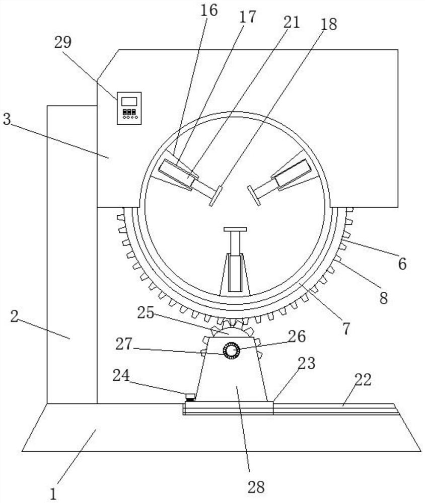
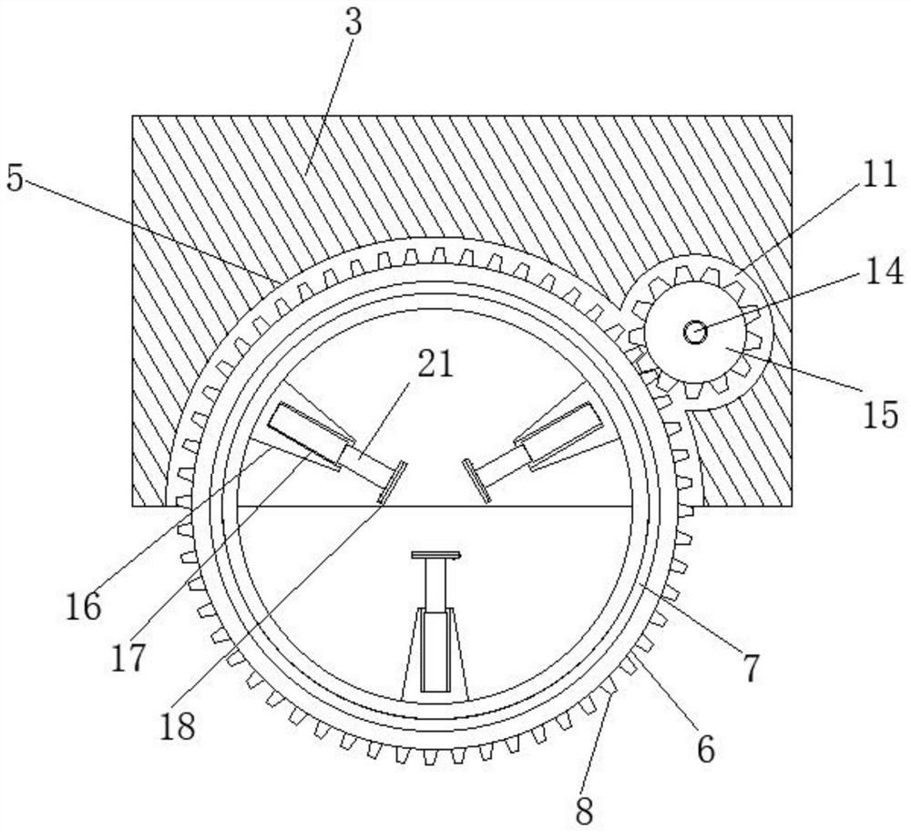
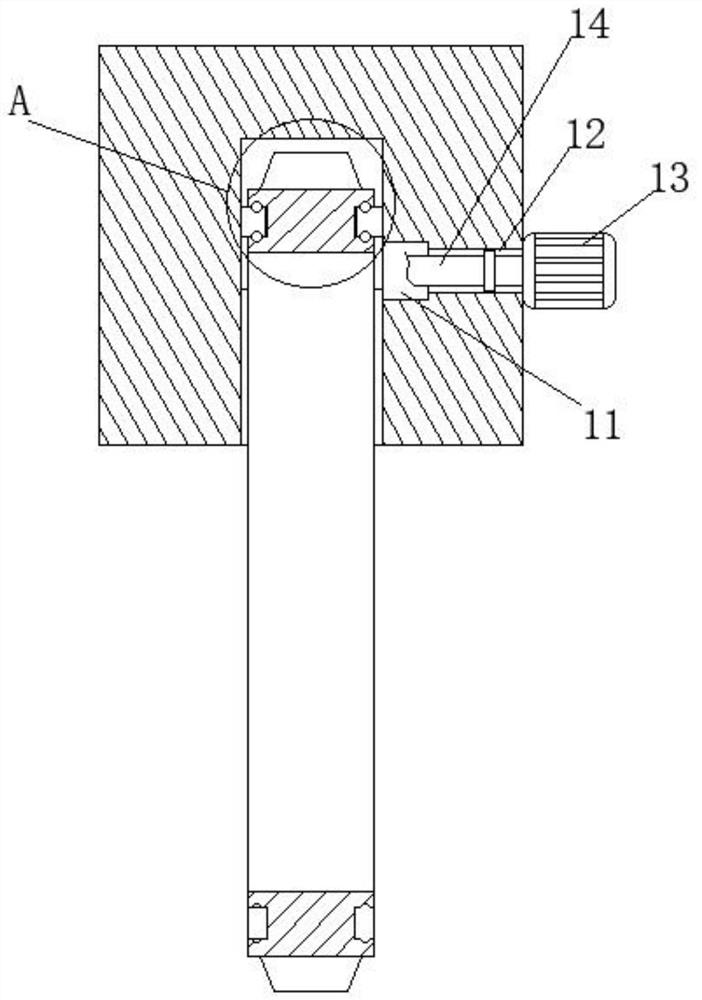
[0033] A new turning device for mechanical processing, comprising a base 1 and a ring 6, a support frame 2 is provided on one side of the top end of the base 1, and a mounting plate 3 is provided on the top end of one side of the support frame 2, and the mounting plate 3 The middle part of the bottom end is sunken upwards to form a mounting groove 5, and the circular ring 6 is rotatably installed inside the mounting groove 5, and both side walls of the circular ring 6 are provided with a ring-shaped limiting groove 7, so that The outer circumferential wall of the ring 6 is provided with outer teeth 8 distributed in a ring, and the inner walls of both sides of the installation groove 5 are equipped with a limit block 9 that is slidably connected with the limit groove 7, and the inside of the installation plate 3 is opened. There is a side groove 11, and one side outer wall of the mo...


PUM


Abstract

The invention relates to the field of machining techniques, and particularly relates to a novel machining turnover device, which comprises a base and a circular ring, wherein one side of the top end of the base is provided with a supporting frame; further, the top end of one side of the supporting frame is provided with a mounting plate; a mounting groove is formed in the middle of the bottom endof the mounting plate in an upward sinking manner; the circular ring is rotationally mounted inside the mounting groove; the side walls of the two sides of the circular ring are both provided with limiting grooves which are of annular structures; the circumferential outer wall of the circular ring is provided with outer teeth distributed annularly; and the inner walls of the two sides of the mounting grooves are both provided with limiting blocks connected with the limiting grooves in a sliding manner. By using the novel machining turnover device, the disadvantages in the prior art are overcome; by starting air cylinders, bottom plates mounted at output ends of the air cylinders are enabled to extend and retract; thus, the three bottom plates are enabled to approach oppositely; further, clamping plates fixed to the bottom plates are driven to mutually approach to clamp and fix a to-be-machined member; the three clamping plates are used for triangularly fixing the to-be-machined member;and the to-be-machined member is fixed more stably.

Description

technical field [0001] The invention relates to the field of mechanical processing, in particular to a novel turning device for mechanical processing. Background technique [0002] Machining refers to the process of changing the shape or performance of a workpiece through a mechanical device. According to the difference in processing methods, it can be divided into cutting processing and pressure processing. During the machining process, the workpiece needs to be turned over, so as to facilitate the processing of the workpiece. [0003] After searching, the patent with publication number CN209190356U discloses a turning device for mechanical processing, which includes a base, the top right side of the base is provided with a first chute, and the inside of the first chute is flexibly connected to the second chute. A first slider matched with a chute, the top of the first slider is fixedly connected with a first vertical plate, the top of the first vertical plate is fixedly c...

Claims


Application Information

Patent Timeline
IPC IPC(8): B23Q3/08B23Q3/154B23Q5/28
CPCB23Q3/08B23Q3/15B23Q5/28
Inventor 赖剑峰张金新
Owner 惠安县钗新汽车配件中心
Learn More