Replaceable injection head mechanism for full-electric injection machine

An injection head and injection machine technology, applied in the field of injection molding machines, can solve problems such as hidden safety hazards, inconvenient installation and replacement methods, etc., and achieve the effects of easy operation, improved practicability, and simple and convenient operation.

Pending Publication Date: 2020-09-25
张家港市联鑫塑料机械有限公司
View PDF0 Cites 2 Cited by
  • Summary
  • Abstract
  • Description
  • Claims
  • Application Information

AI Technical Summary

Problems solved by technology

[0004] The purpose of the present invention is to provide a replaceable injection head mechanism for an all-electric injection machine, to solve the problem that most of the existing injection heads proposed in the background technology connect the injection port with the injection mechanism through welding or hot melting. When it needs to be installed or replaced, the staff needs to assist the positioning of the injection port and install it with external tools. This installation and replacement method is inconvenient and has certain safety hazards.

Method used


Image

  • Replaceable injection head mechanism for full-electric injection machine
  • Replaceable injection head mechanism for full-electric injection machine
  • Replaceable injection head mechanism for full-electric injection machine

Examples


Embodiment Construction

[0026] The following will clearly and completely describe the technical solutions in the embodiments of the present invention with reference to the accompanying drawings in the embodiments of the present invention. Obviously, the described embodiments are only some, not all, embodiments of the present invention. Based on the embodiments of the present invention, all other embodiments obtained by persons of ordinary skill in the art without making creative efforts belong to the protection scope of the present invention.

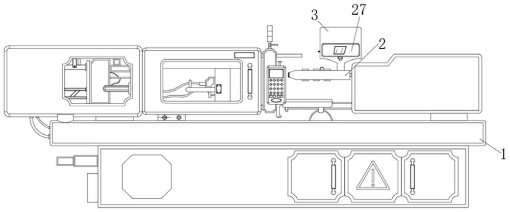
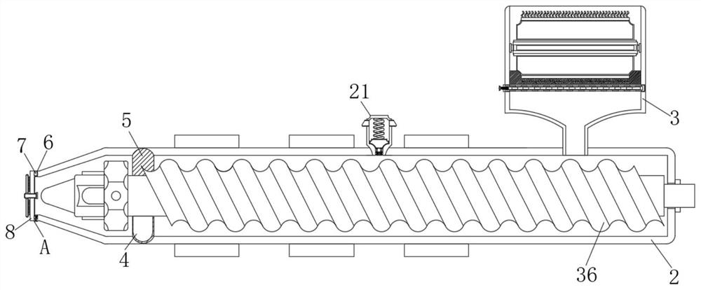
[0027] see Figure 1-8 , an embodiment provided by the present invention:

[0028] A replaceable injection head mechanism for an all-electric injection machine, including an injection molding machine body 1, an injection chamber 2, and a feeding screw 36. The right side of the top of the injection chamber 2 is fixed with a feed chamber 3, and the left side of the feed chamber 3 A second slot 22 is provided, the inside of the second slot 22 is inserted with a ...


PUM


Abstract

The invention discloses a replaceable injection head mechanism for a full-electric injection machine. The replaceable injection head mechanism comprises an injection molding machine body, an injectionbin and a feeding screw rod, wherein a feeding bin is fixedly arranged on the right side of the top end of the injection bin, a pressure relief mechanism is fixedly arranged at the top end of the injection bin, a first inserting groove is formed in the bottom end of the left side of the injection bin, an injection head is arranged on the left side of the injection bin, and a second sliding grooveis formed in the top end of the left side of the injection bin. According to the replaceable injection head mechanism, a movable push block is pressed, the movable push block moves upwards in a limiting groove, when the movable push block moves to a certain position, the movable push block is attached to a limiting inserting rod, at the moment, force is continuously applied to a pressing push rod, so that the movable push block drives the limiting inserting rod to press a first compression spring and the compression spring contracts inwards, when the limiting inserting rod moves to a certainposition, the limiting inserting rod is not connected with the limiting groove for limiting any more, at the moment, the injection head can be held and pulled outwards, then the injection head and theinjection bin can be disassembled, so that the injection head can be replaced, the operation is simple and convenient, and the operation and the use of workers are facilitated.

Description

technical field [0001] The invention relates to the technical field of injection molding machines, in particular to a replaceable injection head mechanism for an all-electric injection machine. Background technique [0002] Injection machine is injection molding machine or injection molding machine. It is the main molding equipment for making thermoplastics or thermosetting plastics into various shapes of plastic products using plastic molding molds. The injection mechanism is one of the indispensable components of the injection machine. , Generally, there are three main forms of "plunger type, screw type, screw pre-molded plunger injection type", and the most widely used is the screw type. Its working principle is that in a cycle of the injection molding machine, a certain amount of plastic can be heated and plasticized within a specified time, and under a certain pressure and speed, the molten plastic is injected from the injection head into the mold cavity through the scr...

Claims


Application Information

Patent Timeline
Patent Type & Authority Applications(China)
IPC IPC(8): B29C45/18B29C45/20B29C45/63B29C45/47B29C45/17
CPCB29C45/17B29C45/1773B29C45/18B29C45/20B29C45/47B29C45/63
Inventor 何志斌倪爱明任巧安
Owner 张家港市联鑫塑料机械有限公司
Why Eureka
Try Eureka