
Pipefitting die with runner without retardation and forming method thereof

A molding method and a technology for pipe fittings, which are applied to household appliances, tubular objects, and other household appliances, can solve problems such as high stress, and achieve the effects of ensuring production efficiency, broad market prospects, and industrial development advantages

Pending Publication Date: 2020-09-25
卢秀章
View PDF0 Cites 0 Cited by
  • Summary
  • Abstract
  • Description
  • Claims
  • Application Information

AI Technical Summary

Problems solved by technology

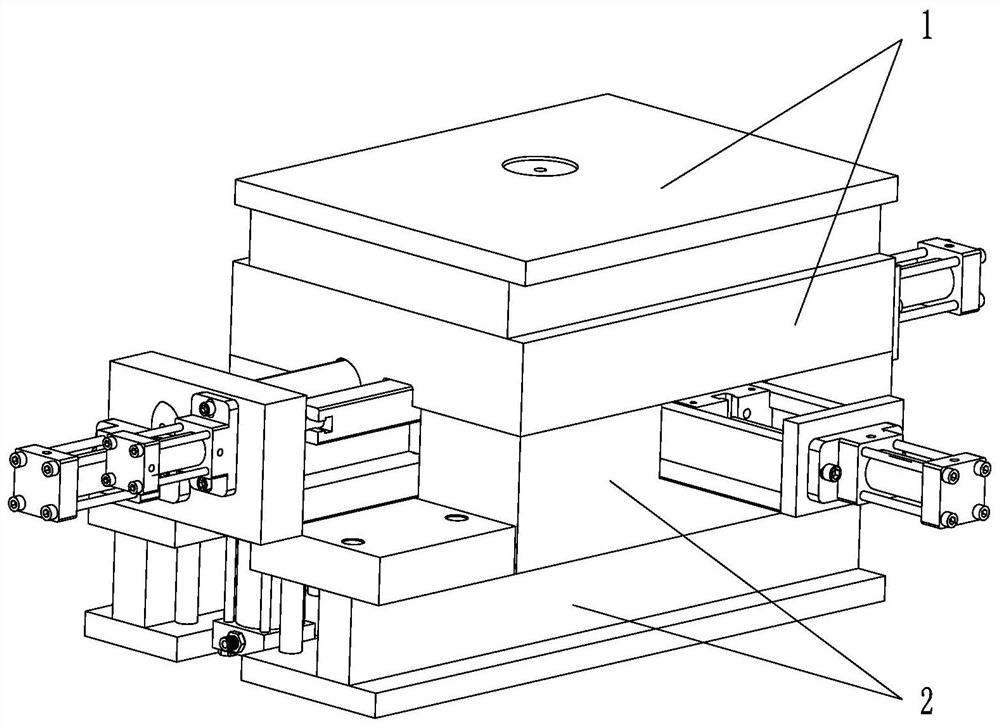
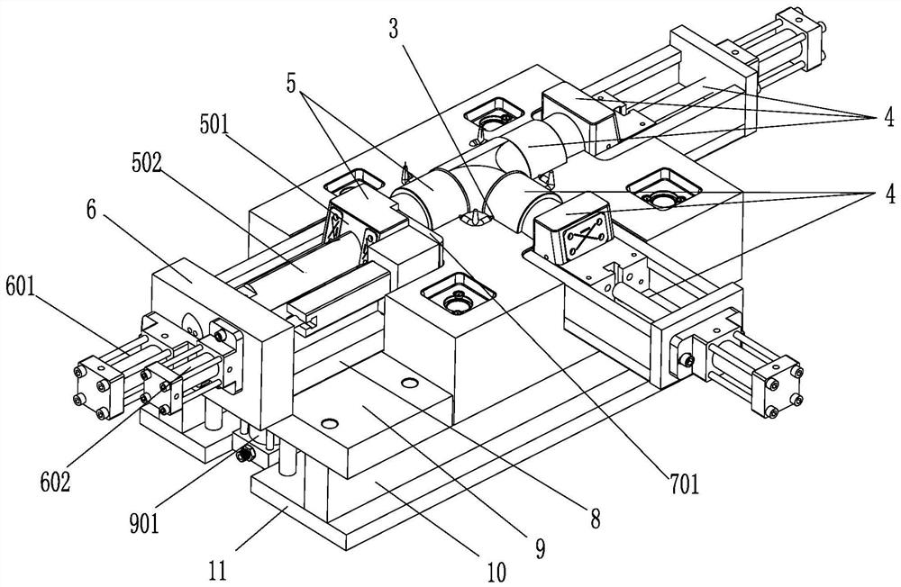
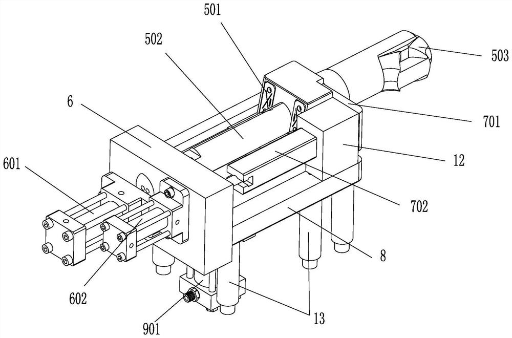
[0005] Provide a flow channel non-blocking pipe fitting mold and a forming method thereof, the flow channel non-blocking pipe fitting mold includes a movable mold matched with the fixed mold and a cavity formed between the fixed mold and the movable mold, and is characterized in that: According to the characteristics of the product to be produced, the mold cavity is provided with several core slider combinations corresponding to it arranged on the mold cavity, and the several core slider combinations are all arranged on different sides of the movable mold, One side of the movable mold is provided with a core slider combination, including but not limited to a main core slider guide rail cooperating action unit, which is used to cooperate with other said core slider combinations to be produced The product is demoulded after molding; the main core slider guide rail matching unit includes a main core slider, and a central rod is arranged in the main core slider, and the front end of the central rod is combined with other core sliders A forming insert is provided at the joint of the cores, and the main core slide slides on the central rod; the product to be produced is selected to adopt the corresponding forming insert, obviously, including its shape; the end of the central rod is fixed On the tailstock frame located on one side of the moving mold, the tailstock frame is also provided with a first oil cylinder, and the first oil cylinder is connected with the main core slider; that is, the main cylinder is controlled by the first oil cylinder The core slider moves forward or backward on the central rod to complete product molding or demoulding; in order to adapt to the situation where the relative stress of some products to be produced is relatively large, the guide rail of the main core slider cooperates with the action unit The same side is also provided with a unit for pushing the product off, and the unit for pushing the product off includes a mechanical pusher, and the mechanical pusher is connected with the second oil cylinder provided on the tailstock frame, and is connected with the main core slider Arranged in the same direction, it is convenient for the main core slider to reset after the straight three-way pipe fittings are formed, and it protrudes forward to eject the product; in order to overcome the insufficient space height difference caused by the space between the cavity and the product, the product will be ejected Difficulties in mold output; set a demoulding height supplementary jacking unit, the demoulding height supplementary jacking unit includes a third oil cylinder, the third oil cylinder is arranged on the bottom side of the movable mold and fixed on the movable mold On the mould, the third oil cylinder is connected with the supporting plate connected and fixed with the tailstock frame; the third oil cylinder lifts the supporting plate and the tailstock frame as a whole, and drives the The main core slider guide rail cooperating unit and / or the pushing product drop-off unit move upwards, so that when the product is demolded, it is lifted from the initial position of the cavity to generate a relative displacement difference, that is, a height difference, which facilitates the product to come out and increases the production efficiency of the product. degree of automation;

Method used


Image

  • Pipefitting die with runner without retardation and forming method thereof
  • Pipefitting die with runner without retardation and forming method thereof
  • Pipefitting die with runner without retardation and forming method thereof

Examples


Embodiment Construction

[0035] Describe below in conjunction with above accompanying drawing, but at least should not be limited to following embodiment of the present invention:

[0036] See attached figure 1 to attach Figure 9 , firstly provide a pipe fitting mold with no blockage in the flow channel, specifically as attached figure 1 Straight tee flow path unrestricted pipe fitting mold shown, and see attached figure 2 , which includes a movable mold 2 matched with its fixed mold 1 and a cavity 3 formed between the fixed mold 1 and the movable mold 2. The cavity 3 is provided with corresponding The two permanent core slider combinations 4 arranged on the cavity 3 and one main core slider guide rail in the present invention cooperate with the action unit, and the two core slider combinations 4 and one main core slider The block guide rails cooperate with the action units to be arranged on different sides of the movable mold 2, and its position distribution can be found in the attached figure...


PUM


Abstract

The invention relates to a pipefitting die with a runner without retardation and a forming method thereof. The pipefitting die comprises a movable die matched with a fixed die and a cavity formed between the fixed die and the movable die. A plurality of core and slide block combinations arranged on the cavity correspondingly are arranged on the cavity according to characteristics of to-be-producedproducts. The core and slide block combinations are arranged on different sides of the movable die, wherein one core and slide block combination arranged on one side of the movable die includes, butnot limited to, a main core and slide block guide rail matched action unit for being coordinated with other core and slide block combinations to act so as to demold the to-be-produced products after compression molding; and a demolding height compensation jacking unit is further arranged on the die or a product push falling unit is selectively arranged on the die. The forming method comprises thefour steps. By arranging various related pipefitting dies, a forming insert is designed fully, so that it is ensured that various pipefitting products produced are utilized and the runner is free of aretardation phenomenon. The product includes, but not limited to, a straight three-way pipefitting or an inclined three-way pipefitting or a right-angle elbow pipe.

Description

technical field [0001] The present invention relates to the field of pipe fitting moulds, in particular to a mold for forming pipe fitting runners, including its molding method; specifically, after the pipe fittings produced by the mold are connected and matched with the mouth of a plastic connecting pipe, Its flow path is smooth and unobstructed. Background technique [0002] After the injection-molded pipe fittings are connected with the pipes, the blockage of the flow channel has always been a concern of the mold industry. Therefore, on the basis of the existing technology, it has been innovated many times; the traditional drainage socket pipe fitting mold, The horseshoe structure is used to solve the problem of blockage of the flow channel, the applicable surface is narrow, the shape is limited, and it is not suitable for the manufacture of multi-standard pipe fittings; there is also a mold core with a large arc demoulding structure, which is only suitable for socket p...

Claims


Application Information

Patent Timeline
Patent Type & Authority Applications(China)
IPC IPC(8): B29C45/33B29C45/44B29L23/00
CPCB29C45/33B29C45/4435B29L2023/00
Inventor 卢秀章
Owner 卢秀章
Learn More