Motorcycle accelerator handle structure and motorcycle

A motorcycle oil and door handle technology, which is applied to bicycle accessories, transportation and packaging, bicycle control systems, etc., can solve the problems of reduced zipper tightness, poor throttle handle feel, and inability to adjust the ratio, so as to facilitate layout and improve feel , increase the adjustment effect

Pending Publication Date: 2020-09-25
河北在路上摩托车配件科技有限公司
View PDF0 Cites 1 Cited by
  • Summary
  • Abstract
  • Description
  • Claims
  • Application Information

AI Technical Summary

Problems solved by technology

[0003] In the existing zipper structure, the ratio of the rotation angle of the throttle coil to the stroke of the zipper is fixed, and this ratio cannot be adjusted, which may be difficult to

Method used


Image

  • Motorcycle accelerator handle structure and motorcycle
  • Motorcycle accelerator handle structure and motorcycle
  • Motorcycle accelerator handle structure and motorcycle

Examples


Embodiment 1

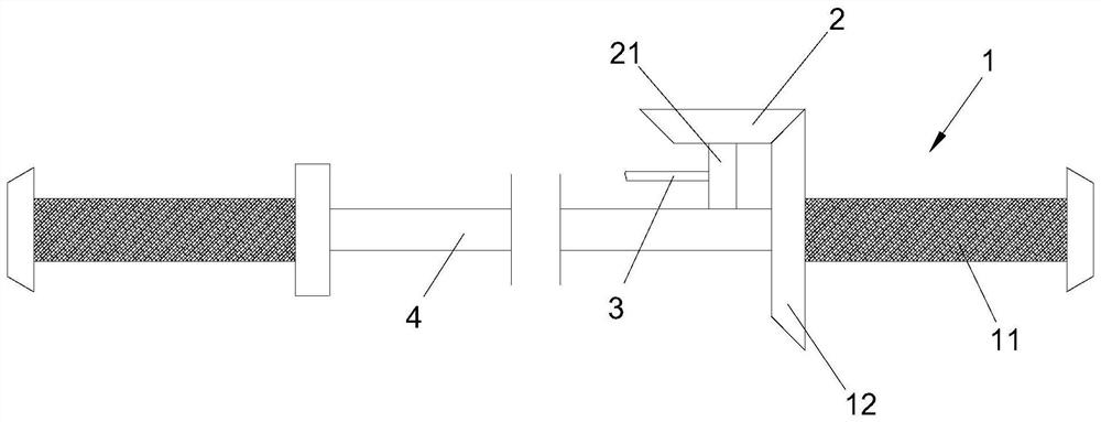
[0032] This embodiment relates to a motorcycle throttle handle structure, which is arranged on the body of the motorcycle, and includes a rotatable throttle coil 1 arranged on the vehicle body, and a transmission unit 2 connected with the throttle coil 1. The unit 2 can be driven by the rotation of the throttle coil 1 to pull the throttle zipper 3; the throttle coil 1 includes a rotatable bushing section 11 arranged on the vehicle body, and a first gear 12 fixed on the bushing section 11, The transmission unit 2 includes a second gear that is rotated on the vehicle body and meshes with the first gear 12. The above-mentioned bushing section 11 can be driven by an external force to drive the first gear 12 and the second gear to rotate. The rotation of the second gear can be Pull the throttle lock 3.

[0033] refer to figure 1 As shown, the first gear 12 of the present embodiment is fixed on one end of the casing section 11, specifically on an inner end of the casing section 11,...

Embodiment 2

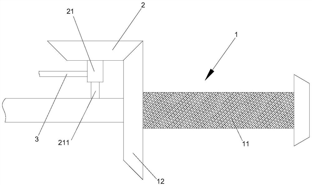
[0042] This embodiment relates to a motorcycle throttle handle structure, which has roughly the same structure as the motorcycle throttle handle structure described in Embodiment 1, the difference lies in: figure 2 As shown, the second gear shaft 21 of this embodiment includes several shaft sections 211 with different diameters connected in series, and the aforementioned throttle zipper 3 can be selectively connected with one of the shaft sections 211. It should be noted that the throttle zipper 3. For the way of connecting with each shaft section 211, please refer to the way of connecting the throttle zipper and the second gear shaft 21 in the first embodiment, so it will not be repeated here.

[0043] The motorcycle accelerator handle structure of the present embodiment, by setting the second gear shaft 21 to include shaft sections 211 with unequal diameters, when the throttle zipper 3 is connected with the shaft sections 211 of different diameters, when the throttle coil ro...

Embodiment 3

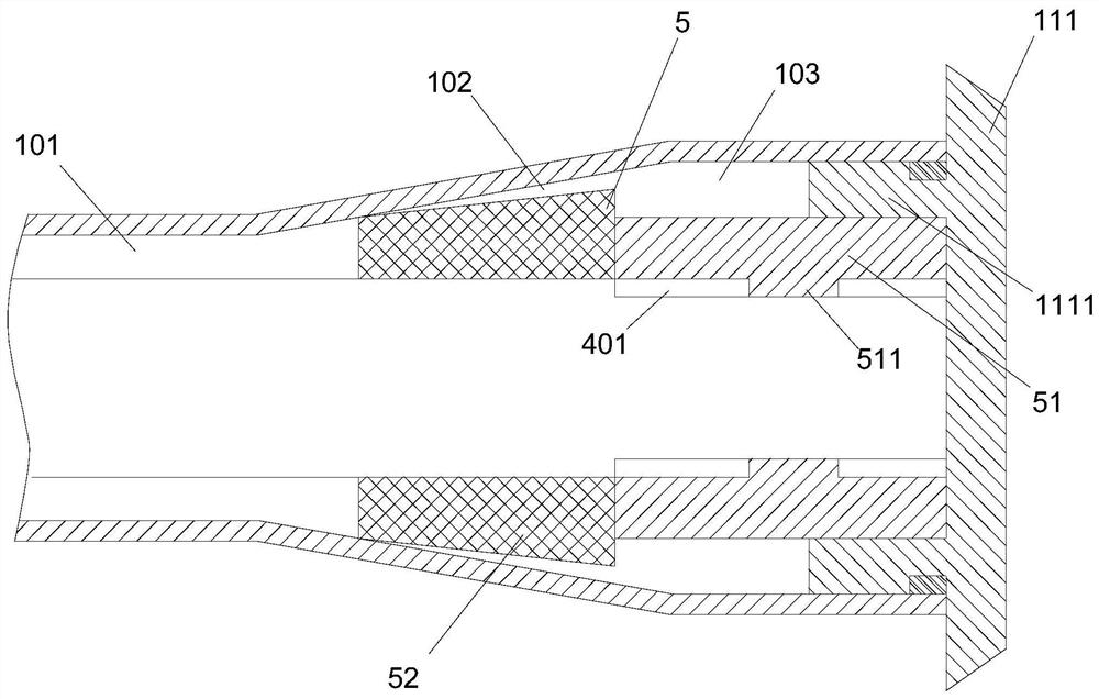
[0045] This embodiment relates to a motorcycle throttle handle structure, which has roughly the same structure as the motorcycle throttle handle structure of Embodiment 1 or Embodiment 2, the difference lies in: in this embodiment, the casing section 11 and the vehicle body A damping unit 5 is arranged therebetween for applying a damping force to the rotation of the bushing section 11 relative to the handle rod 4 . Preferably, the damping force provided by the damping unit 5 is set to be adjustable.

[0046] The sleeve section 11 of this embodiment specifically includes a sleeve body, and a rotatable knob 111 arranged on the sleeve body; , the above-mentioned damping unit 5 includes a rubber pad sandwiched between the side wall of the tapered hole and the handle rod 4 , and the rubber pad can be driven by the rotation of the knob 111 to move along the axial direction of the tapered hole.

[0047] For specific structure, refer to image 3 As shown, from one end of the casing ...


PUM


Abstract

The invention provides a motorcycle accelerator handle structure which is arranged on a motorcycle body and comprises an accelerator coiled pipe rotatably arranged on the motorcycle body and a transmission unit connected with the accelerator coiled pipe. The transmission unit can be driven by rotation of the accelerator coiled pipe to pull an accelerator zipper. The accelerator coiled pipe comprises a sleeve section which is rotatably arranged on the vehicle body and a a first gear fixedly arranged on the sleeve section in a sleeving mode; the transmission unit comprises a second gear which isrotatably arranged on the vehicle body and can be meshed with the first gear, the sleeve section can bear an external force to drive the first gear and the second gear to rotate, and the acceleratorzipper can be pulled by the rotation of the second gear. The accelerator handle structure of the motorcycle has good control hand feeling.

Description

technical field [0001] The invention relates to the technical field of motorcycle components, in particular to a motorcycle throttle handle structure, and also relates to a motorcycle with the motorcycle throttle handle structure applied thereto. Background technique [0002] The throttle adjustment operation of the motorcycle is completed through the throttle handle. The throttle handle includes a handle switch assembly and a rotatable throttle coil arranged on the handle switch assembly. The front end of the throttle coil is provided with a lock seat, and one end of the lock is fixed on the On the zipper seat, the other end is connected to the throttle. During use, the throttle can be adjusted by turning the throttle coil to pull the zipper. [0003] In the existing zipper structure, the ratio of the rotation angle of the throttle coil to the stroke of the zipper is fixed, and the ratio cannot be adjusted, which may be difficult to meet the rider's need for throttle feel, ...

Claims


Application Information

Patent Timeline
IPC IPC(8): B62K23/04
CPCB62K23/04
Inventor 张夏夏
Owner 河北在路上摩托车配件科技有限公司
Why Eureka
Try Eureka