Tubular connecting piece for cast-in-place concrete wall and heat preservation plate with tubular connecting piece

A technology of concrete walls and connectors, applied in the direction of insulation, walls, building components, etc., can solve the problems of the decline of wall insulation performance, achieve the effects of reducing heat loss, improving insulation performance, and reducing the number

Pending Publication Date: 2020-09-25
山东赛昌新型材料有限公司
View PDF0 Cites 0 Cited by
  • Summary
  • Abstract
  • Description
  • Claims
  • Application Information

AI Technical Summary

Problems solved by technology

[0005] The invention provides a tubular connector for cast-in-situ concrete walls and a thermal insulation board with the tubular connector, which solves the problem of thermal insulation of the wall caused by opening holes on the thermal insulation board for setting connectors and pull bolts in the prior art. The problem of slow performance

Method used


Image

  • Tubular connecting piece for cast-in-place concrete wall and heat preservation plate with tubular connecting piece
  • Tubular connecting piece for cast-in-place concrete wall and heat preservation plate with tubular connecting piece
  • Tubular connecting piece for cast-in-place concrete wall and heat preservation plate with tubular connecting piece

Examples


Embodiment 1

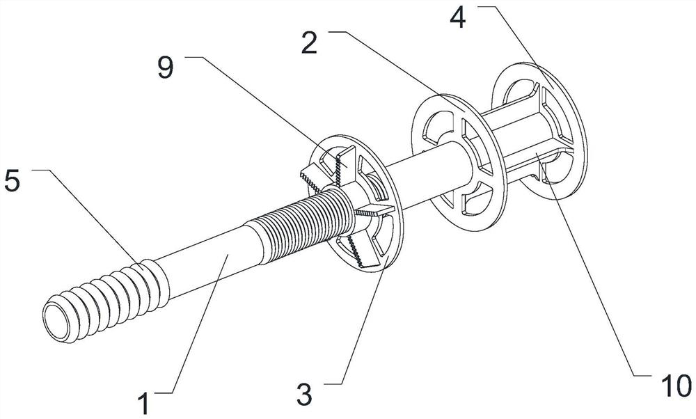
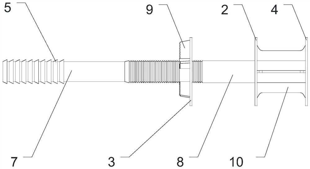
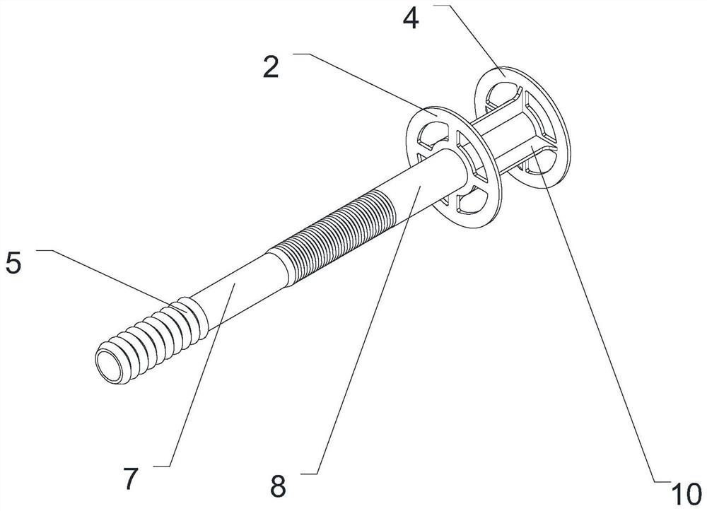
[0042] Such as Figure 1-4 As shown, the tubular connector for cast-in-place concrete walls includes a pipe body 1, the axial passage of the pipe body 1 runs through the pipe body 1 to form openings at both ends of the pipe body 1, and the outer wall of the pipe body 1 is provided with a first stop Sheet 2 and the second limiting sheet 3. When the present invention is in use, the pipe body 1 passes through the insulation board, and the two ends respectively lean against the inner formwork and the outer formwork to support the inner and outer formworks. The fastening of pull bolts realizes the fixation of the inner and outer templates. There is no need to make special holes on the insulation board when setting the pull bolts, which reduces the number of through holes on the insulation board, reduces heat loss, and improves the insulation performance of the wall. The first limiting piece 2 and the second limiting piece 3 sandwich the insulation board in the middle, keep the po...

Embodiment 2

[0046] The difference between this embodiment and Embodiment 1 is that the end piece 4 is fixedly connected with the tube body 1, the first limiting piece 2 is integrally formed with the tube body 1, the outer wall of the tube body 1 is provided with a buckle structure, and the second limiting piece The piece 3 is detachably connected with the tube body 1 through a buckle structure. The embedded structure 5 is a bump. The outer wall of the pipe body 1 is provided with an embedded structure 5, and the length along the axial direction of the pipe body 1 is 8 cm.

Embodiment 3

[0048] The difference between this embodiment and Embodiment 1 is that the outer wall of the tube body 1 is provided with a barb structure, and the second limiting piece 3 is connected with the tube body 1 through the barb structure. The embedded structure 5 is a barb.


PUM


Abstract

The invention relates to the field of building formwork connecting and supporting, and solves the problem that in the prior art, holes are formed in a heat preservation plate to arrange a connecting piece and a split bolt, and consequently the heat preservation performance of a wall is reduced. A tubular connecting piece for a cast-in-place concrete wall comprises a tube body, an axial channel ofthe tube body penetrates through the tube body to form openings in the two ends of the tube body, and a first limiting piece and a second limiting piece are arranged on the outer side wall of the tubebody. When the tubular connecting piece is used, the tube body penetrates through the heat preservation plate, the two ends of the tube body are abutted against an inner formwork and an outer formwork respectively, the inner formwork and the outer formwork are supported, the split bolt penetrates through the axial channel in the tube body, and the split bolt is fastened to fix the inner formworkand the outer formwork. When the split bolt is arranged, holes do not need to be specially formed in the heat preservation plate, the number of through holes in the heat preservation plate is reduced,heat losses are reduced, and the heat preservation performance of the wall is improved.

Description

technical field [0001] The invention relates to the field of connection and support of building templates, in particular to a tubular connector for cast-in-situ concrete walls and a thermal insulation board with the tubular connector. Background technique [0002] The cast-in-place concrete built-in thermal insulation wall refers to the wall made by binding steel bars, on-site formwork, pouring concrete, curing, and removing the formwork. When pouring concrete, in order to fix the inner and outer formwork, it is necessary to open holes on the insulation board. Connectors and pull bolts. The rod body of the connector is a solid rod body, which needs to be set separately from the tension bolts. There are a large number of connectors and tension bolts. Usually, 6-8 connectors and 9 tension bolts need to be installed per square meter. There are 15-17 through holes on the insulation board. The cast-in-place concrete wall structure is inner wall layer-insulation board-outer wall ...

Claims


Application Information

Patent Timeline
Patent Type & Authority Applications(China)
IPC IPC(8): E04B2/00E04B2/84E04B1/76E04B1/80
CPCE04B1/76E04B1/80E04B2/00E04B2/84
Inventor 刘文起
Owner 山东赛昌新型材料有限公司
Why Eureka
Try Eureka