
Clamping piece installation accessory

A technology of auxiliary parts and clips, which is applied in the field of clip installation accessories, can solve the problems of anchorage failure, difficulty in ensuring the distance between clips, deep bite marks, etc., and achieve the effects of simple operation, improved reliability and convenient positioning

Active Publication Date: 2020-09-25
威胜利工程有限公司
View PDF17 Cites 0 Cited by
  • Summary
  • Abstract
  • Description
  • Claims
  • Application Information

AI Technical Summary

Problems solved by technology

During construction, it is difficult to manually position the clips to ensure that the clips are evenly spaced, resulting in uneven bite between the circumference of the steel strand and the clips. If the gap between the clips is too small and the bite marks are too deep, the steel strand may be damaged early, resulting in Anchorage failure

Method used


Image

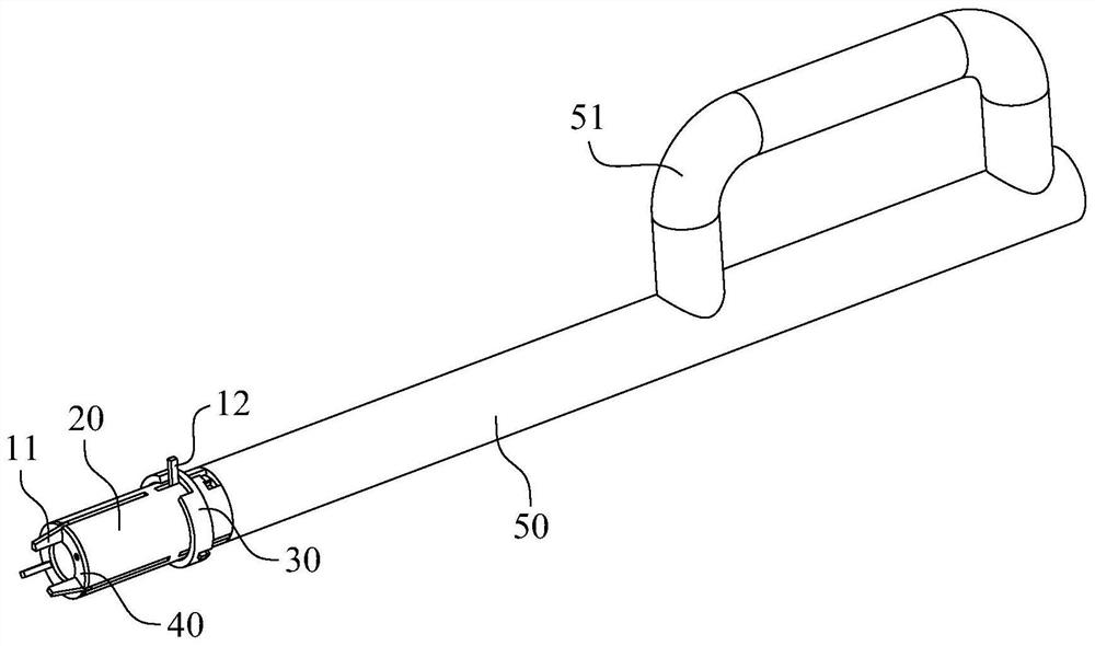
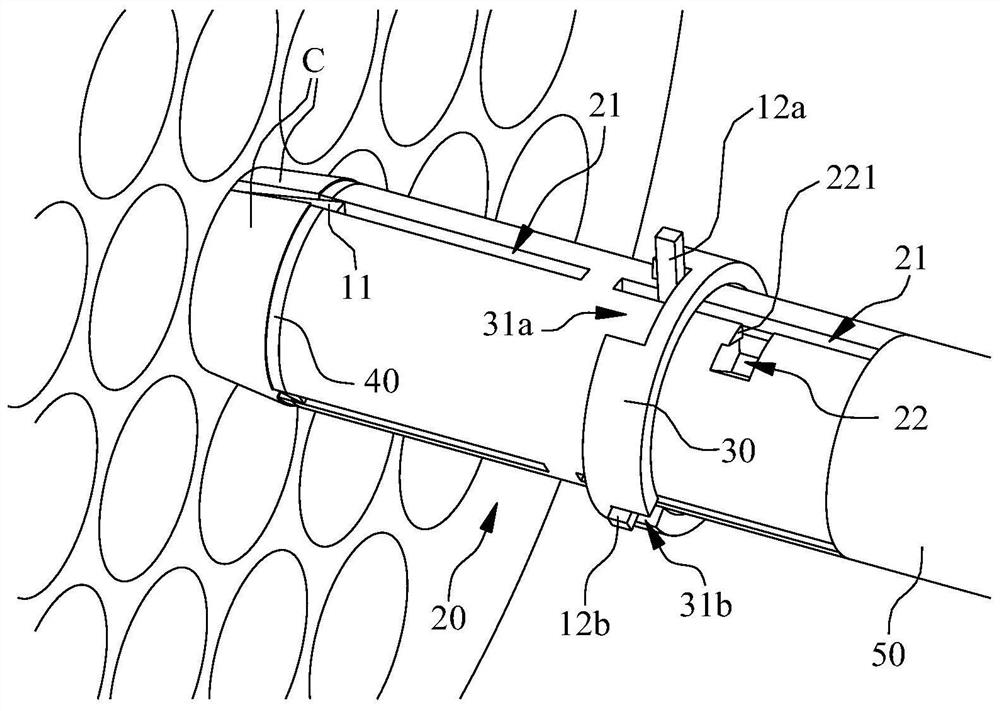
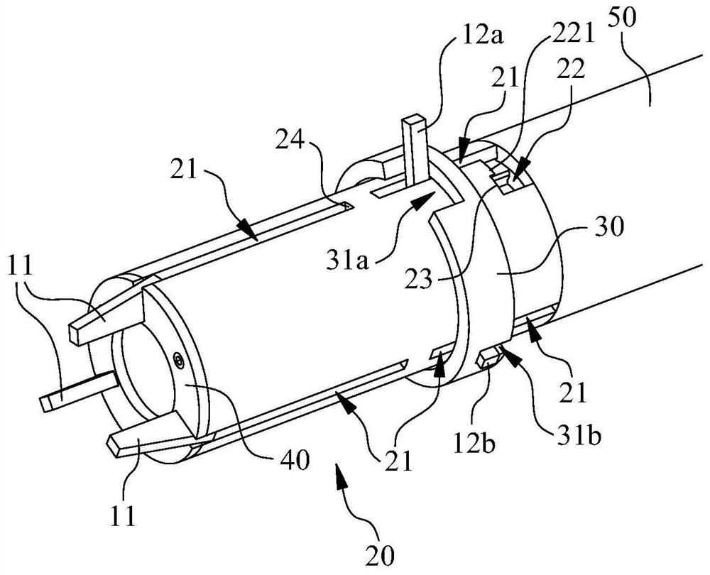
  • Clamping piece installation accessory
  • Clamping piece installation accessory
  • Clamping piece installation accessory

Examples


Embodiment Construction

[0019] The specific implementation manner of the present invention will be further described in detail below by describing the embodiments in conjunction with the accompanying drawings.

[0020] For ease of description, the front side or front end adjacent to the clip C is defined, and the back side or rear end away from the clip C is defined.

[0021] A clip installation accessory, including a tube base 20 with a separator 11 symmetrically arranged in the circumferential direction, the tube base 20 and the separator 11 form a position-limiting displacement fit along the tube length direction of the tube base 20, and the separator 11 extends to the tube There is a displacement between an overhang position outside the tube end of the base 20 and a retracted position retracted into the tube base 20 . Such as figure 2 As shown, when the separator 11 is in the overhanging position, it is inserted between the clips C, which can ensure the minimum distance between two adjacent cli...


PUM


Abstract

The invention belongs to the technical field of engineering construction, and particularly relates to a clamping piece installation accessory. The clamping piece installation accessory comprises a tube base with separation pieces symmetrically arranged in the circumferential direction, the tube base and the separation pieces form limiting displacement fit in the tube length direction of the tube base, the separation pieces move between an overhanging position extending out of the tube end of the tube base and a retracting position retracting into the tube base, and the sectional dimensions ofthe separation pieces along the circumferential direction of the tube base are the same. When the separation pieces are located at the overhanging position, the separation pieces are matched with clamping pieces, the minimum distance of the clamping pieces can be guaranteed, and after the clamping pieces are preliminarily positioned, the separation pieces are driven to move to the retracting position, and then subsequent anchoring operation can be completed. The clamping piece installation accessory is easy to operate, the clamping pieces are convenient to position, and the reliability of an anchoring system can be greatly improved.

Description

technical field [0001] The invention belongs to the technical field of engineering construction, in particular to a clip installation auxiliary part. Background technique [0002] In the clip-type prestressed anchoring system, the internal wire teeth of the clip are engaged with the surface of the steel strand, and the outside of the clip is matched with the tapered hole of the anchorage. The steel strand is stretched so that the clip moves along with the steel strand toward the tapered hole. The displacement of the small diameter end realizes the anchoring of the steel strand. In the prior art, for an anchoring structure using three-lobed clips matched with steel strands, gaps are reserved between adjacent clips. The smaller the gap, the greater the bite force between the clips on both sides and the steel strand, and the deeper the bite marks. During construction, it is difficult to manually position the clips to ensure that the clips are evenly spaced, resulting in uneve...

Claims


Application Information

Patent Timeline
IPC IPC(8): E04G21/12
CPCE04G21/12
Inventor 柏国清徐金志郝玉柱张雷陈登凯王泽永李厚宝胡娟
Owner 威胜利工程有限公司
Learn More