Rectifying and reinforcing device for preventing inclination of combined house
A technology for combining houses and reinforcing devices, which is applied in building maintenance, infrastructure engineering, sheet pile walls, etc., can solve problems such as the inability to combine houses for reinforcement, and achieve the effect of good deviation correction and reinforcement and excellent seismic effect.
- Summary
- Abstract
- Description
- Claims
- Application Information
AI Technical Summary
Problems solved by technology
Method used
Image

Examples
Embodiment 1
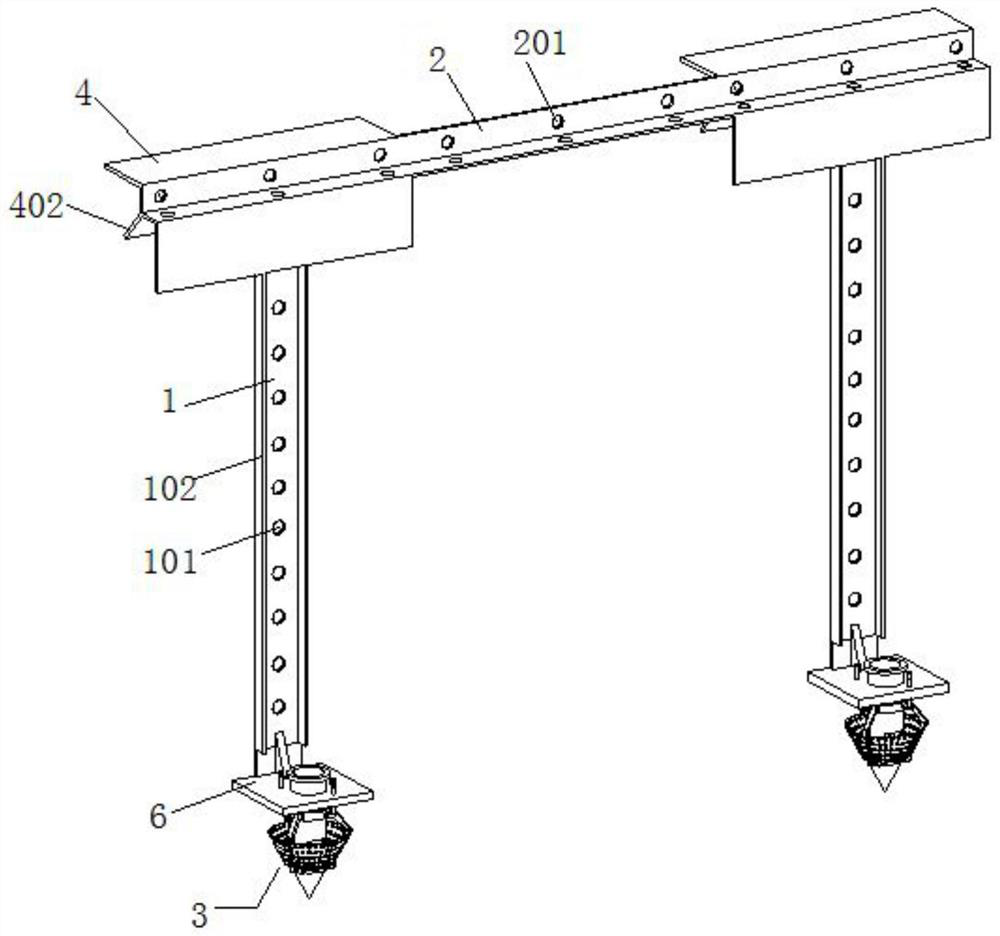
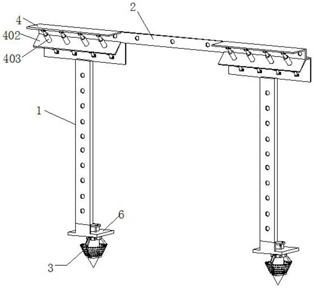
[0032] Embodiment 1 introduces a kind of deflection correction and reinforcement device for anti-tilting of composite houses, please refer to the attached figure 1 And attached figure 2 As shown, its main structure includes a main keel reinforcement profile 1 , an auxiliary keel reinforcement profile 2 and foundation fixing piles 3 . Wherein the cross-section of the auxiliary keel reinforcement profile 2 is L-shaped, and both sides of the auxiliary keel reinforcement profile 2 are provided with a number of first connection holes 201, and the first connection holes 201 are evenly spaced on both sides of the auxiliary keel reinforcement profile 2 .
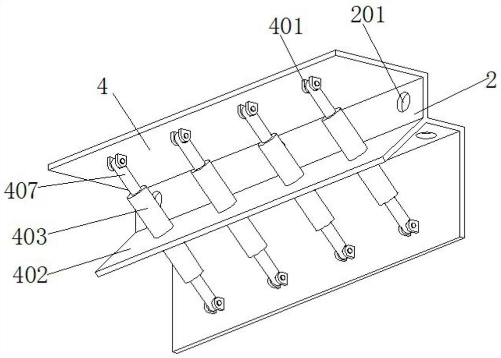
[0033] Reference attached image 3 As shown, two auxiliary keel connecting plates 4 are connected to the left and right ends of the auxiliary keel reinforcement profile 2, specifically, the two auxiliary keel connection plates 4 are respectively connected to the two side outer ends of one end of the auxiliary keel reinforcement p...
Embodiment 2
[0038] Embodiment 2 introduces an improved deflection correction and reinforcement device for anti-tilting composite buildings based on Embodiment 1. Please refer to the attached figure 1 And attached figure 2 As shown, its main structure includes a main keel reinforcement profile 1 , an auxiliary keel reinforcement profile 2 and foundation fixing piles 3 . Wherein the cross-section of the auxiliary keel reinforcement profile 2 is L-shaped, and both sides of the auxiliary keel reinforcement profile 2 are provided with a number of first connection holes 201, and the first connection holes 201 are evenly spaced on both sides of the auxiliary keel reinforcement profile 2 .
[0039] Reference attached image 3 As shown, two auxiliary keel connecting plates 4 are connected to the left and right ends of the auxiliary keel reinforcement profile 2, specifically, the two auxiliary keel connection plates 4 are respectively connected to the two side outer ends of one end of the auxili...
PUM
 Abstract
Description
Claims
Application Information
 - Generate Ideas
- Intellectual Property
- Life Sciences
- Materials
- Tech Scout
- Unparalleled Data Quality
- Higher Quality Content
- 60% Fewer Hallucinations
Browse by: Latest US Patents, China's latest patents, Technical Efficacy Thesaurus, Application Domain, Technology Topic, Popular Technical Reports.
© 2025 PatSnap. All rights reserved.Legal|Privacy policy|Modern Slavery Act Transparency Statement|Sitemap|About US| Contact US: help@patsnap.com