
Image correction and correction data generation method, device, system and display method

A technology for data correction and image correction, applied in image data processing, image enhancement, image analysis, etc., to achieve the best correction effect and uniform brightness and chromaticity.

Active Publication Date: 2021-04-02
XIAN NOVASTAR TECH
View PDF4 Cites 3 Cited by
  • Summary
  • Abstract
  • Description
  • Claims
  • Application Information

AI Technical Summary

Problems solved by technology

The introduction of the AM driving method will inevitably lead to more obvious non-linearity of LED display, and more diverse forms of Mura (that is, uneven display) of LEDs. Therefore, an image correction and display method that can be applied to various driving methods is required. In order to achieve better calibration and display effect

Method used


Image

  • Image correction and correction data generation method, device, system and display method
  • Image correction and correction data generation method, device, system and display method
  • Image correction and correction data generation method, device, system and display method

Examples


no. 1 example

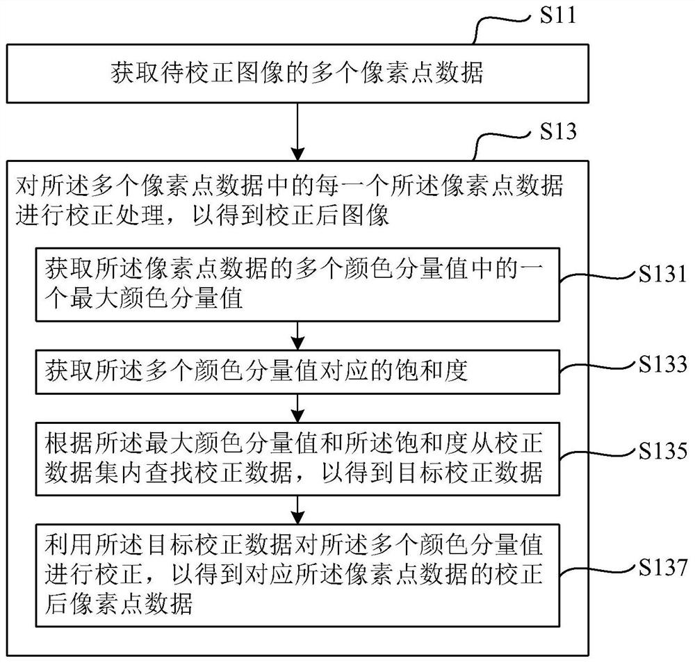
[0038] Such as figure 1 As shown, an image correction method provided by the first embodiment of the present invention includes steps:

[0039] S11: Obtain multiple pixel point data of the image to be corrected;

[0040] S13: Perform correction processing on each of the plurality of pixel data to obtain a corrected image.

[0041] Wherein, the step S13 specifically includes sub-steps:

[0042] S131: Obtain a maximum color component value among multiple color component values ​​of the pixel data;

[0043] S133: Acquire saturations corresponding to the multiple color component values;

[0044] S135: Search for correction data from the correction data set according to the maximum color component value and the saturation, so as to obtain target correction data;

[0045] S137: Correct the multiple color component values ​​by using the target correction data, so as to obtain corrected pixel point data corresponding to the pixel point data.

[0046] Optionally, as an embodiment ...

no. 2 example

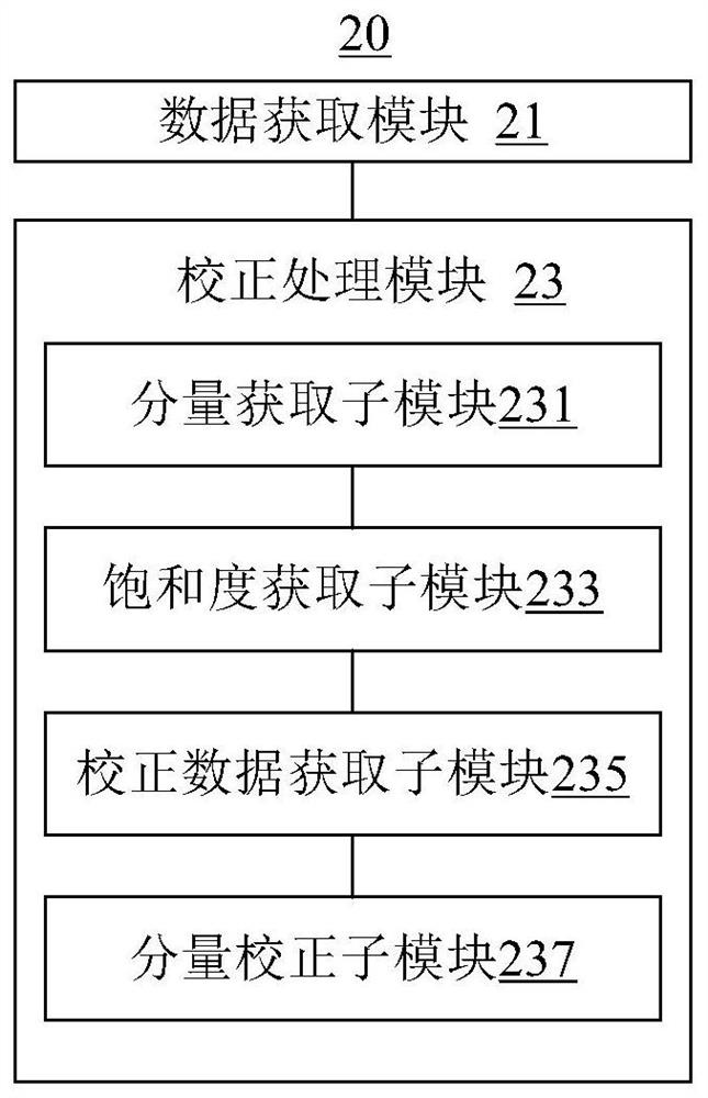
[0070] Such as figure 2 As shown, an image correction device 20 provided by the second embodiment of the present invention includes: a data acquisition module 21 and a correction processing module 23 . Wherein, the correction processing module 23 includes a component acquisition sub-module 231 , a saturation acquisition sub-module 233 , a correction data acquisition sub-module 235 and a component correction sub-module 257 .

[0071] Wherein, the data acquisition module 21 is, for example, used to acquire a plurality of pixel point data of the image to be corrected; and the correction processing module 23 is used, for example, to perform Correction processing to obtain the corrected image. Wherein, the component acquisition sub-module 231 is, for example, used to acquire a maximum color component value among the multiple color component values ​​of the pixel point data; the saturation acquisition sub-module 233 is, for example, used to acquire the multiple color component val...

no. 3 example

[0077] Such as Figure 5As shown, an image correction system 500 provided by the third embodiment of the present invention includes: a processor 51 and a memory 53 electrically connected to the processor 51; wherein, the memory 53 stores instructions executable by the processor 51, and the instructions For example, the processor 51 is made to perform operations to perform the image correction method described in the aforementioned first embodiment.


PUM


Abstract

The embodiment of the invention relates to an image correction and correction data generation method, a device, a system and an image display method. The image correction method comprises the following steps: acquiring data of a plurality of pixel points of a to-be-corrected image; and performing correction processing on each piece of pixel point data to obtain a corrected image, and specificallycomprises the steps of obtaining a maximum color component value in a plurality of color component values of the pixel point data, and obtaining saturations corresponding to the plurality of color component values, and searching correction data from a correction data set according to the maximum color component value and the saturation degree to obtain target correction data, and correcting the plurality of color component values by using the target correction data to obtain corrected pixel point data corresponding to the pixel point data. According to the embodiment of the invention, different correction data can be selected according to the color component values of the pixel point data, and proper correction data can be selected for correction, so as to achieve a better correction effect.

Description

technical field [0001] The present invention relates to the technical field of image display and correction, in particular to an image correction method, an image correction device, an image correction system, a correction data generation method, a correction data generation device and an image display method. Background technique [0002] With the development of LED display technology, LED display screens have been applied to various fields due to their advantages of low cost, low power consumption, high visibility, and freedom of assembly. At the same time, with the popularization of LED display applications, people have higher and higher requirements for its display quality. Therefore, how to improve the display quality of LED display screens has become a research hotspot in this field. [0003] One of the more difficult problems at present is that the brightness and chromaticity uniformity of the image displayed on the LED display screen is relatively poor (that is, ther...

Claims


Application Information

Patent Timeline
Patent Type & Authority Applications(China)
IPC IPC(8): G06T5/00
CPCG06T2207/10024G06T5/92
Inventor 从洪春杨城
Owner XIAN NOVASTAR TECH
Learn More