Variable-step-size rapid high-precision signal demodulation method for optical fiber F-P sensor

A signal demodulation, F-P technology, applied in the direction of converting sensor output, using optical devices to transmit sensing components, instruments, etc., can solve the problems of poor demodulation accuracy, fast demodulation speed, huge calculation amount, etc., to improve demodulation. The effect of high speed, high precision and fast demodulation rate

Inactive Publication Date: 2020-09-25
WUHAN UNIV OF TECH
View PDF5 Cites 0 Cited by
  • Summary
  • Abstract
  • Description
  • Claims
  • Application Information

AI Technical Summary

Problems solved by technology

The Fourier transform demodulation method uses Fast Fourier transform (FFT) to solve the frequency spectrum of the output signal. The demodulation speed is fast, but the demodulation accuracy is poor.
The discrete cavity length demodulation algorithm constructs a series of virtual cavity length values ​​at a certain step interval within a cavity length range, and compares the spectral signals of different virtual cavity lengths with the actual spectral signals. When the accuracy is high, this method exists The problem of huge amount of calculation is not suitable for practical application

Method used


Image

  • Variable-step-size rapid high-precision signal demodulation method for optical fiber F-P sensor
  • Variable-step-size rapid high-precision signal demodulation method for optical fiber F-P sensor
  • Variable-step-size rapid high-precision signal demodulation method for optical fiber F-P sensor

Examples


Embodiment Construction

[0031] In order to better explain the present invention and facilitate understanding, the present invention will be described in detail below through specific embodiments in conjunction with the accompanying drawings.

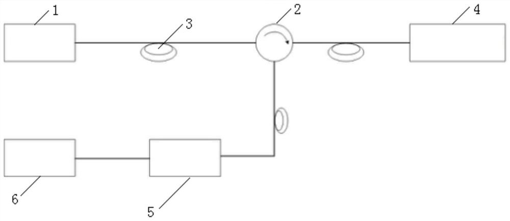
[0032] The present invention improves a fast and high-precision signal demodulation method of an optical fiber F-P sensor with a variable step size. The structural diagram of the optical fiber F-P sensing system is as follows figure 1 As shown, it includes a broadband light source 1, a circulator 2, an optical fiber 3, an optical fiber F-P sensor 4, a spectrum acquisition module 5 and a computer 6. The central wavelength of the broadband light source 1 is 850nm, and the 3dB bandwidth is 40nm. The light emitted by the broadband light source 1 is transmitted to the optical fiber F-P sensor 4 through the optical fiber 3 and the circulator 2, and the reflected optical signal enters the spectrum acquisition module 5 through the circulator 2, and the spectrum acquisit...


PUM


Abstract

The invention relates to a variable-step-size rapid high-precision signal demodulation method for an optical fiber F-P sensor. The method comprises the following steps: preprocessing a spectral signalreceived by an optical fiber F-P sensor to obtain a normalized spectrum sequence in a discrete form; carrying out demodulating by using a fast Fourier transform method to obtain a cavity length roughvalue; constructing a series of virtual cavity lengths and corresponding interference spectrums thereof in a virtual cavity length simulation range with a relatively large step size; calculating meansquare errors between the virtual spectrums with different cavity size values and real spectrums; acquiring a virtual cavity length value corresponding to the minimum mean square error, then reducingthe virtual cavity length simulation range and step size, calculating the mean square error of the virtual cavity length and the actual spectrum to find out the cavity length value corresponding to the minimum mean square error, and repeating the steps in sequence until the demodulation precision requirement is met to obtain a final cavity length value. According to the method, absolute measurement of the cavity length of the optical fiber F-P sensor can be realized, the demodulation speed is high, and the cavity length resolution is high.

Description

technical field [0001] The invention relates to the technical field of optical fiber sensing, in particular to a fast and high-precision signal demodulation method of an optical fiber F-P sensor with variable step size. Background technique [0002] For fiber optic F-P sensors, the quality of the signal demodulation method directly affects the response speed and detection accuracy of the sensing system. At present, signal demodulation methods can be roughly divided into two types: intensity demodulation method and phase demodulation method. In the intensity demodulation method, the system often uses a narrow linewidth light source or a monochromatic laser light source to ensure a constant light wavelength. The change of light intensity and cavity length in the working area is linear for demodulation, and the demodulation speed is fast, which is suitable for measuring dynamic signals such as vibration and sound wave frequency. The phase demodulation method is to obtain the r...

Claims


Application Information

Patent Timeline
Patent Type & Authority Applications(China)
IPC IPC(8): G01D5/353
CPCG01D5/35312
Inventor 童杏林陈续之方定江张翠邓承伟
Owner WUHAN UNIV OF TECH
Why Eureka
Try Eureka