Reflection type spectral pupil differential confocal-photoacoustic microimaging device and method

A differential confocal and photoacoustic microscopy technology, applied in the direction of microscopes, optics, optical components, etc., can solve problems such as the inability to realize cell structure images, and achieve the effects of absolute measurement, improved signal-to-noise ratio, and easy miniaturization

Active Publication Date:
View PDF12 Cites 4 Cited by
  • Summary
  • Abstract
  • Description
  • Claims
  • Application Information

AI Technical Summary

Problems solved by technology

However, the resolution of photoacoustic imaging is only up to 10 microns, and it cannot realize structural images at the cellular level

Method used


Image

  • Reflection type spectral pupil differential confocal-photoacoustic microimaging device and method
  • Reflection type spectral pupil differential confocal-photoacoustic microimaging device and method
  • Reflection type spectral pupil differential confocal-photoacoustic microimaging device and method

Examples


Embodiment 1

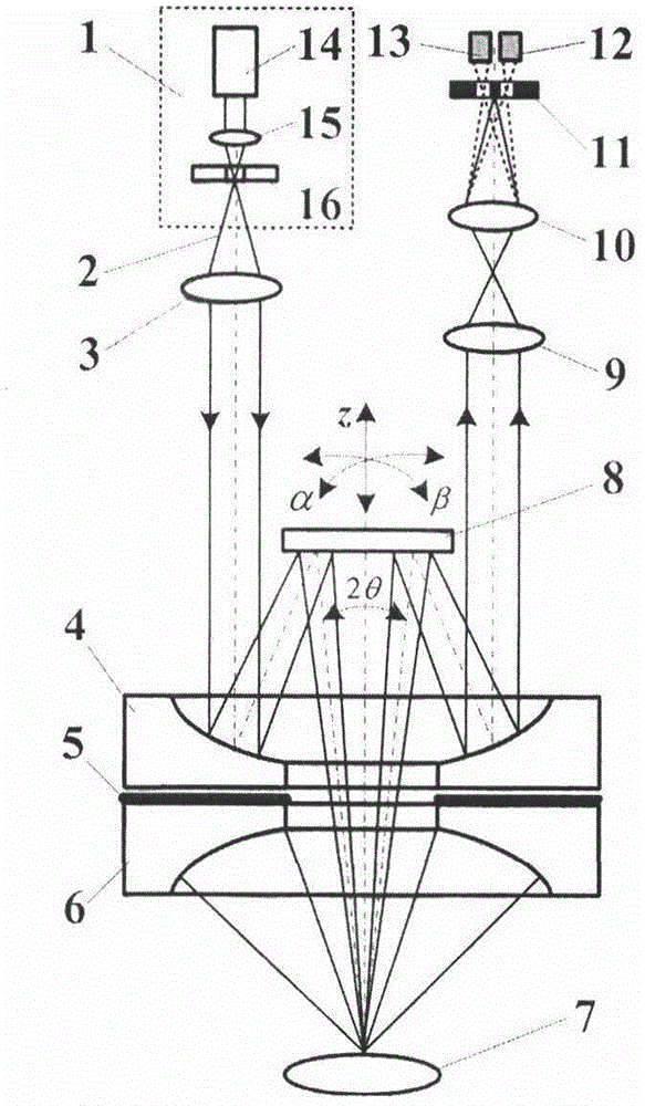
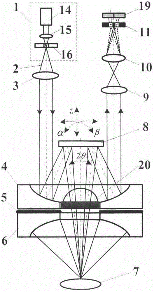
[0041] The embodiment of the present invention is based on Figure 4 The reflective split-pupil differential confocal-photoacoustic microscopy imaging device shown includes a point light source system 1 composed of a laser 14, a focusing mirror 15 placed in the laser emission direction, and a pinhole 16 placed at the focal point of the focusing mirror 15. , the collimating lens 3, reflective condenser 4, three-dimensional beam scanner 8, aberration compensating hemispherical mirror 20 and the measured object 7 are sequentially placed in the traveling direction of the pulsed beam 2, and are sequentially placed in the backscattering direction of the measured object 7 to detect An acoustic lens 6 and an ultrasonic transducer 5 for photoacoustic signals, and a reflective split-pupil differential confocal detection system for detecting backscattered light or fluorescence signals of the measured object 7; wherein the reflective split-pupil differential confocal The detection system ...

Embodiment 2

[0084] like figure 1 As shown, in the reflective split-pupil differential confocal-photoacoustic microscopy imaging device of Embodiment 1, the CCD detector 17 is replaced by a double-hole pinhole located on the focal plane of the relay lens and placed symmetrically with the double hole axis 11 , and the first light intensity detector 12 and the second light intensity detector 13 located behind the double-hole pinhole 11 detect the scattered light or fluorescence signal of the excited object 7 to be measured.

[0085] All the other measuring methods are the same as in Example 1.

Embodiment 3

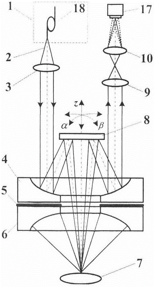
[0087] like figure 2 As shown, in the reflective split-pupil differential confocal-photoacoustic microscopy imaging device of Embodiment 1, the point light source system 1 is replaced by a fiber exiting point light source 18 .

[0088] All the other measuring methods are the same as in Example 1.


PUM


Abstract

The invention relates to a reflection type spectral pupil differential confocal-photoacoustic microimaging device and method, and belongs to the field of confocal microimaging technologies and photoacoustic microimaging technologies. The structures and the functions of a spectral pupil differential confocal microimaging system and a photoacoustic imaging system are organically combined; the spectral pupil differential confocal microimaging system is used for detecting spatial structure information of a biological sample, and the photoacoustic microimaging system is used for detecting functional information of the biological sample, so that simultaneous detection of the spatial structure information and the functional information of the biological sample can be realized, and in-situ and noninvasive real-time imaging of a biological living body is expected to be realized. By adoption of a spectral pupil differential confocal imaging technology, the axial resolution and the working distance of the spectral pupil differential confocal-photoacoustic microimaging device can be effectively compatible, so that interference of stray light on a focal surface can be suppressed; the signal-to-noise ratio of the system is high; therefore, integrated and handheld design of the spectral pupil differential confocal-photoacoustic microimaging device can be facilitated.

Description

technical field [0001] The invention relates to a reflective split-pupil differential confocal-photoacoustic microscopic imaging device and method, belonging to the technical fields of confocal microscopic imaging technology and photoacoustic microscopic imaging technology. technical background [0002] Due to its unique tomographic imaging capability and high spatial resolution capability in the optical field, confocal microscopy imaging technology has been widely used as an important technical means in biomedical research, physical chemistry research, material testing, micro-nano testing and other fields. However, the existing confocal microscopic imaging technology mainly uses the scattered light or fluorescence of the object for imaging, which only obtains the structural image of the observed object, and cannot obtain the functional image of cells or biological macromolecules. The depth is only on the order of submillimeters. [0003] Photoacoustic imaging is based on t...

Claims


Application Information

Patent Timeline
Patent Type & Authority Applications(China)
IPC IPC(8): G02B21/00G02B21/06A61B5/00
CPCG02B21/0024G02B21/0032G02B21/0052
Inventor 赵维谦邱丽荣
Why Eureka
Try Eureka