Pressure sensing module, touch control assembly, electronic equipment and touch control method

A technology of sensing modules and touch components, applied in the direction of electrical digital data processing, instruments, data processing input/output process, etc., can solve problems such as unsatisfactory requirements, achieve simple structure, convenient manufacture, and reduce overall volume Effect

Inactive Publication Date: 2020-09-25
NANCHANG OUFEI BIOLOGICAL IDENTIFICATION TECH
View PDF0 Cites 0 Cited by
  • Summary
  • Abstract
  • Description
  • Claims
  • Application Information

AI Technical Summary

Problems solved by technology

[0004] However, the above-mentioned touch screen products cannot meet the public's increasing demand for advanced human-computer interaction in smart devices

Method used


Image

  • Pressure sensing module, touch control assembly, electronic equipment and touch control method
  • Pressure sensing module, touch control assembly, electronic equipment and touch control method
  • Pressure sensing module, touch control assembly, electronic equipment and touch control method

Examples


Embodiment 1

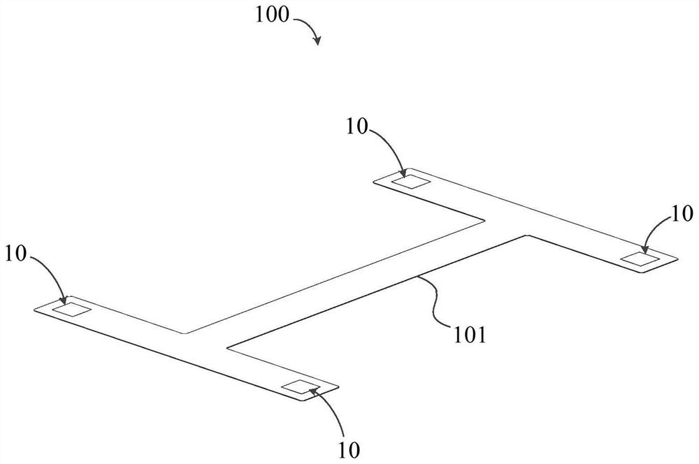
[0070] refer to Figure 1 to Figure 8 As shown, the present embodiment provides a pressure sensing module 100 . The pressure sensing module 100 includes: at least one set of pressure sensing structures 10, each set of pressure sensing structures 10 includes at least two piezoresistors 11, and the at least two piezoresistors 11 are connected in series to form a loop.

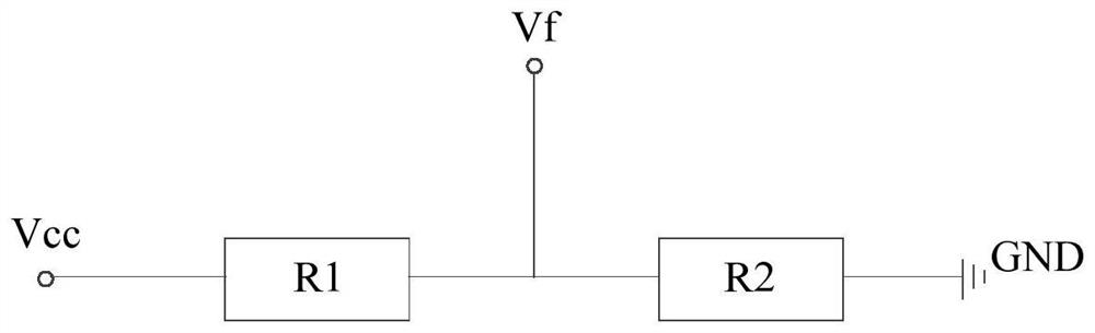
[0071] Wherein, the piezoresistor part 11 can be deformed under the action of pressing, so that the resistance value of the piezoresistor part 11 changes with the change of deformation, and then the voltage component on the piezoresistor part 11 changes; wherein, Different voltage component values ​​are used to correspond to different control commands.

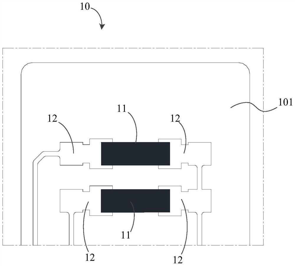
[0072] refer to figure 2 and image 3 As shown, the pressure sensing structure 10 includes two piezoresistor parts 11 as an example for description, wherein one piezoresistor part 11 (for example figure 2 located above the piezoresistor section 11, that is ...

Embodiment 2

[0101] refer to Figure 4 As shown, this embodiment provides a touch component 200 . The touch component 200 includes: a pressure sensing module 100 and a control board 20 .

[0102] The structure of the pressure sensing module 100 in this embodiment is the same as that of the pressure sensing module 100 provided in the first embodiment, and can bring the same or similar technical effects, which will not be repeated here, and details can be referred to in the first embodiment description of.

[0103] combine Figure 1 to Figure 8 As shown, the pressure sensing module 100 is electrically connected to the control board 20, and the control board 20 is used to generate control commands according to the change value of the voltage component when one of the piezoresistor parts 11 in the pressure sensing structure 10 is pressed.

[0104] It can be understood that when the pressure sensing module 100 includes at least two groups of pressure sensing structures 10 , the at least two gr...

Embodiment 3

[0109] refer to Figure 1 to Figure 8 As shown, this embodiment provides an electronic device 300 . The electronic device 300 includes: a touch panel 30 and a touch component 200 .

[0110] The structure of the touch control component in this embodiment is the same as that of the touch control component 200 provided in the second embodiment, and can bring about the same or similar technical effects, which will not be repeated here.

[0111] which, combined with Figure 5 , Image 6 as well as Figure 7 As shown, the pressure sensing module 100 is specifically disposed inside the touch panel 30 .

[0112] By disposing the pressure sensing module 100 inside the touch panel 30, the pressure sensing module 100 includes at least one set of pressure sensing structures 10, the pressure sensing structure 10 includes at least two piezoresistor parts 11, and the at least two The piezoresistor parts 11 are connected in series to form a loop. When in use, the finger presses the touch...


PUM


Abstract

The invention discloses a pressure sensing module, a touch control assembly, electronic equipment and a touch control method, the pressure sensing module comprises at least one group of pressure sensing structures, each group of pressure sensing structures comprises at least two piezoresistor parts, and the at least two piezoresistor parts are connected in series to form a loop; the piezoresistorparts can deform under the pressing effect, so that the resistance value of the piezoresistor part changes along with the change of the deformation quantity, and then the voltage component on the piezoresistor parts change, wherein different voltage component values are used for corresponding to different control instructions, so that the voltage component values on the piezoresistor parts are changed by controlling the pressure when the piezoresistor parts is pressed, different control functions can be realized by detecting the change of the voltage component values, and the requirements of the public on advanced man-machine interaction are met.

Description

technical field [0001] The invention relates to the technical field of pressure sensing, in particular to a pressure sensing module, a touch component, an electronic device and a touch method. Background technique [0002] With the development of intelligent technology, human-computer interaction technology has become one of the most popular research fields at present, and the recognition of human body's movements using fingers has gradually become the main means of human-computer interaction. [0003] When current touch screen products (such as notebook computers) are in use, fingers touch the touch area of ​​the touch panel or press the left and right keys on the touch panel to realize the touch position positioning and left and right key determination functions. [0004] However, the above-mentioned touch screen products cannot meet the public's increasing demand for advanced human-computer interaction in smart devices. Contents of the invention [0005] The invention ...

Claims


Application Information

Patent Timeline
Patent Type & Authority Applications(China)
IPC IPC(8): G06F3/041G06F3/0354
CPCG06F3/03547G06F3/0412G06F3/0414G06F3/04146
Inventor 李亚飞刘伟缪青
Owner NANCHANG OUFEI BIOLOGICAL IDENTIFICATION TECH
Why Eureka
Try Eureka