A portable seed separator
A separator and portable technology, applied in the field of separators, can solve problems such as low seed separation efficiency
- Summary
- Abstract
- Description
- Claims
- Application Information
AI Technical Summary
Problems solved by technology
Method used
Image
Examples
Embodiment 1
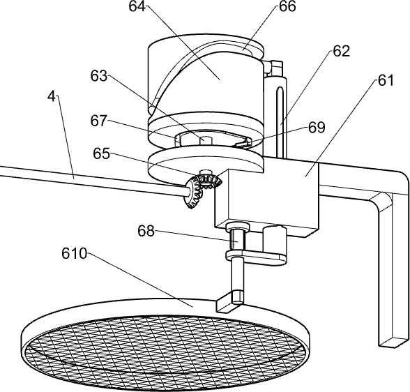
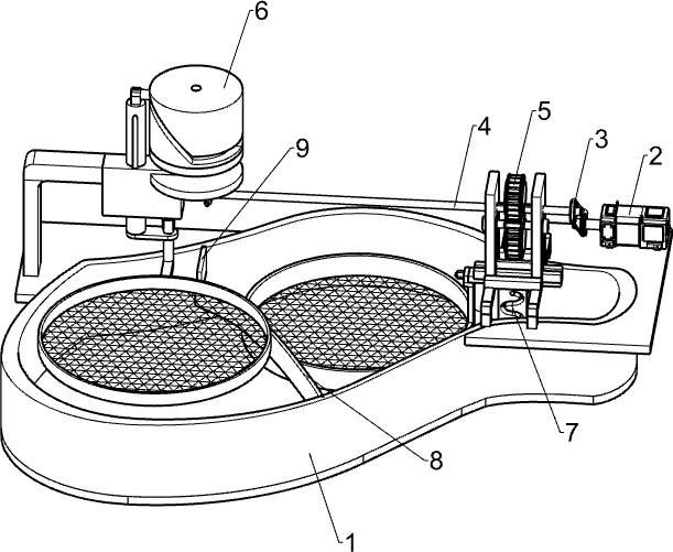
[0034] A portable seed separator such as figure 1 As shown, it includes base 1, motor 2, belt assembly 3, transmission shaft 4, up and down reciprocating mechanism 5 and salvage mechanism 6, motor 2 is installed on the right side of the top of base 1, up and down reciprocating mechanism 5 is arranged on the right side of base 1, reciprocating up and down The components in the mechanism 5 are rotatably provided with a transmission shaft 4, the transmission shaft 4 is located on the left front side of the motor 2, a belt assembly 3 is installed between the output shaft of the motor 2 and the right side of the transmission shaft 4, and a salvage belt assembly is installed on the left side of the top of the base 1. Mechanism 6, fishing mechanism 6 is connected with transmission shaft 4 left sides.
[0035] When the seeds need to be separated, first fill the base 1 with water, put the seeds on the placement parts of the up and down reciprocating mechanism 5, and then start the moto...
Embodiment 2
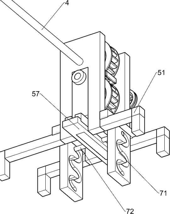
[0037] Specifically, such as Figure 1-3 As shown, the up and down reciprocating mechanism 5 includes a support plate 51, a first gear 52, a second gear 53, a connecting shaft 54, a fixed splint 55, a slide block 56, a slide rail 57, a placement basket 58 and a bolt 581, and the right front side of the base 1 Two support plates 51 are vertically installed, and the transmission shaft 4 is rotatably located on the upper part of the support plates 51. The first gear 52 is eccentrically arranged on the transmission shaft 4 between the support plates 51, and the first gear 52 is covered with a fixed splint 55 The lower part of the support plate 51 on both sides is slidingly equipped with a slider 56, the bottom of the slider 56 is connected with a slide rail 57, and the upper part of the slider 56 on both sides is rotatably provided with a connecting shaft 54, and the eccentric type is arranged on the connecting shaft 54. Second gear 53 is arranged, and second gear 53 meshes with f...
Embodiment 3
[0042] special reference figure 1 and Figure 4 As shown, a swing mechanism 7 is also included. The swing mechanism 7 includes a third guide rail 71 and a guide rod 72. A third guide rail 71 is installed on the front and rear sides of the bottom of the support plate 51. The third guide rail 71 is wave-shaped. The third guide rail 71 The inner sliding type is provided with a guide rod 72, and the guide rod 72 is connected with the middle part of the slide rail 57.
[0043] When the slider 56 moves down, the slider 56 drives the slide rail 57 to move down, and the slide rail 57 drives the guide rod 72 to move down in the third guide rod 72. Under the action of the third guide rail 71, the placement basket 58 moves down. Can swing left and right in middle, when slide block 56 moves up, guide rail moves up in the 3rd guide bar 72, places basket 58 and moves up thereupon and swings left and right, places basket 58 and can be screened to seed in swinging process so that seed can B...
PUM
 Abstract
Description
Claims
Application Information
 - R&D
- Intellectual Property
- Life Sciences
- Materials
- Tech Scout
- Unparalleled Data Quality
- Higher Quality Content
- 60% Fewer Hallucinations
Browse by: Latest US Patents, China's latest patents, Technical Efficacy Thesaurus, Application Domain, Technology Topic, Popular Technical Reports.
© 2025 PatSnap. All rights reserved.Legal|Privacy policy|Modern Slavery Act Transparency Statement|Sitemap|About US| Contact US: help@patsnap.com


