
Screw-up tool for air heater backwater joint on engine water inlet pipe

A water inlet pipe and engine technology, which is applied in workpiece clamping devices, manufacturing tools, hand-held tools, etc., can solve the problems of inconvenient wrench tightening, easy loosening, unstable clamping of legs, etc.

Pending Publication Date: 2020-09-29
Y & C ENGINE
View PDF0 Cites 0 Cited by
  • Summary
  • Abstract
  • Description
  • Claims
  • Application Information

AI Technical Summary

Problems solved by technology

[0004] First: The water inlet pipe is irregular in shape, and the clamping of the legs is unstable, which makes it inconvenient to tighten with a wrench, and it takes time and effort to tighten;
[0005] Second: As a result, the warm air return water joint cannot be tightened, and it is easy to loosen as the car bumps, causing water leakage

Method used


Image

  • Screw-up tool for air heater backwater joint on engine water inlet pipe
  • Screw-up tool for air heater backwater joint on engine water inlet pipe
  • Screw-up tool for air heater backwater joint on engine water inlet pipe

Examples


Embodiment 1

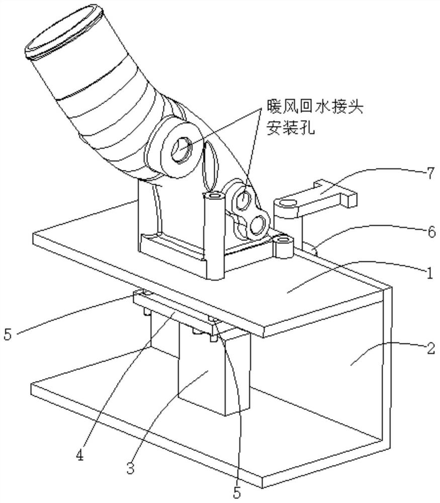
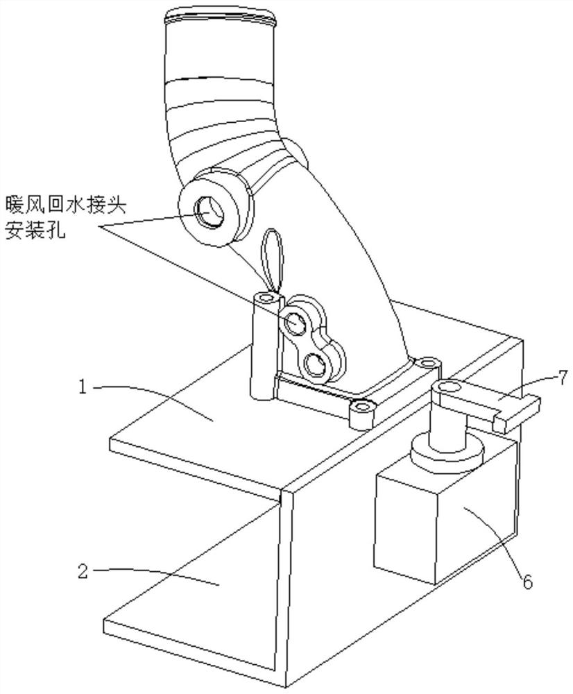
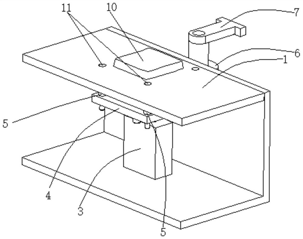
[0033] Tighten the tooling for the warm air return water connector on the water inlet pipe of the engine, first buckle the lower end of the water inlet pipe on the square platform guide seat 10 on the platform board 1, and make the lower end of the water inlet pipe contact with the platform board 1, then start the telescopic cylinder 3, The piston rod of the telescopic cylinder 3 stretches out, pushing the lifting plate 4 to move upwards along the guide rod 13, and the positioning pin 5, which is tightly connected with the lifting plate 4, moves upwards with the lifting plate 4, and the positioning pin 5 moves upward from the guide hole. 11, through the hole at the lower end of the water inlet pipe, and then start the rotary clamping cylinder 6, the piston rod of the rotary clamping cylinder 6 rotates 180 degrees first, so that the clamping head 7 clamps the piston rod of the cylinder 6 with the rotation Rotate 180 degrees above the right side of the water inlet pipe, and then ...

Embodiment 2

[0035] On the basis of Embodiment 1, the platform plate 1 is provided with a four-sided platform guide seat 10, which realizes the blind operation of buckling the water inlet pipe on the four-sided platform guide seat 10, and ensures that the hole at the lower end of the water inlet pipe is in contact with the platform plate. The guide hole 11 on the 1 is aligned; the platform plate 1 is provided with a guide hole 11, and the positioning pin 5 is located in the guide hole 11, which ensures that the positioning pin 5 is located in the guide hole 11 when the piston rod of the telescopic cylinder 3 is in a contracted state. In the first hole 11; the lower end of the platform plate 1 is provided with a connecting plate 12, the lower end of the connecting plate 12 is fastened with a guide rod 13, and the lifting plate 4 is provided with a guide hole 2 14, and the guide rod 13 is connected with the guide hole Two 14 sliding connections ensure the horizontality of the lifting plate 4 ...


PUM


Abstract

The invention discloses a screw-up tool for an air heater backwater joint on an engine water inlet pipe. The screw-up tool comprises a platform plate, a side frame plate, a telescopic air cylinder, alifting plate, positioning pins, a rotary clamping air cylinder and a clamping head. The side frame plate and the side face of the platform plate are in fastening connection, and the telescopic air cylinder and the lower end of the side frame plate are in fastening connection. The lifting plate and the end of a piston rod of the telescopic air cylinder are in fastening connection, the positioningpins and the lifting plate are in fastening connection, the rotary clamping air cylinder and the side wall of the side frame plate are in fastening connection, and the clamping head and the end of a piston rod of the rotary clamping air cylinder are in fastening connection. The clamping and fixing stability of the water inlet pipe is guaranteed, the air heater backwater joint can be screwed up conveniently, time and labor are saved, and screwing up is reliable.

Description

technical field [0001] The invention belongs to the technical field of clamping tooling, in particular, the invention relates to a tooling for tightening a warm air return water joint on an engine water inlet pipe. Background technique [0002] At present, the way for workers to screw the warm air return water connector on the water inlet pipe is to first clamp the water inlet pipe with both legs, then screw the warm air return water connector into the warm air return water connector installation hole on the water inlet pipe, and then use the Wrench to tighten. [0003] The disadvantages of the above installation method are: [0004] First: The water inlet pipe is irregular in shape, and the clamping of the legs is unstable, which makes it inconvenient to tighten with a wrench, and it takes time and effort to tighten; [0005] Second: As a result, the warm air return water joint cannot be tightened, and it is easy to loosen as the car bumps, causing water leakage. Conten...

Claims


Application Information

Patent Timeline
IPC IPC(8): B25B11/02B25B27/14
CPCB25B11/02B25B27/14
Inventor 吴家昌瞿枫汪银屏刘家祥纪鑫祁文胜
Owner Y & C ENGINE
Learn More