A courier auxiliary unloading device
A technology for unloading devices and goods, which is applied in the directions of transportation and packaging, arrangement of loading and unloading vehicles, vehicles used for freight transportation, etc., and can solve the problems of loose and damaged conveyor belts.
- Summary
- Abstract
- Description
- Claims
- Application Information
AI Technical Summary
Problems solved by technology
Method used
Image
Examples
specific Embodiment 1
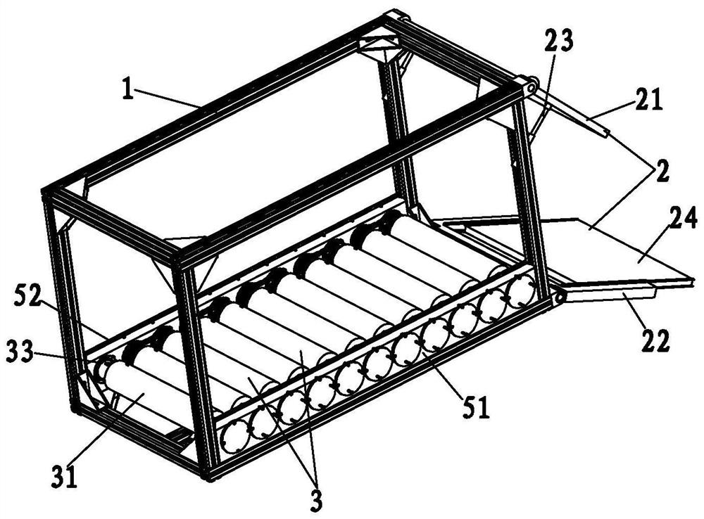
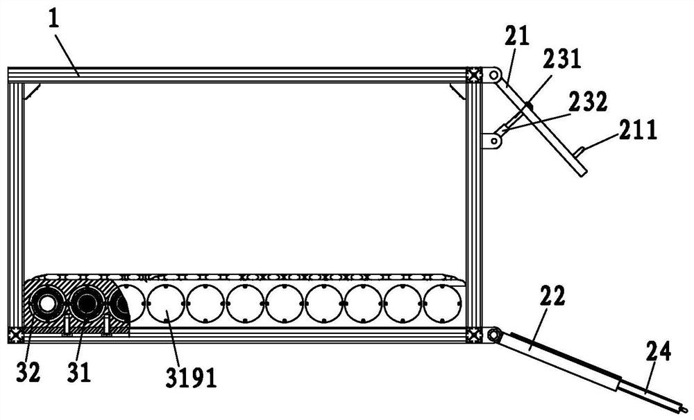
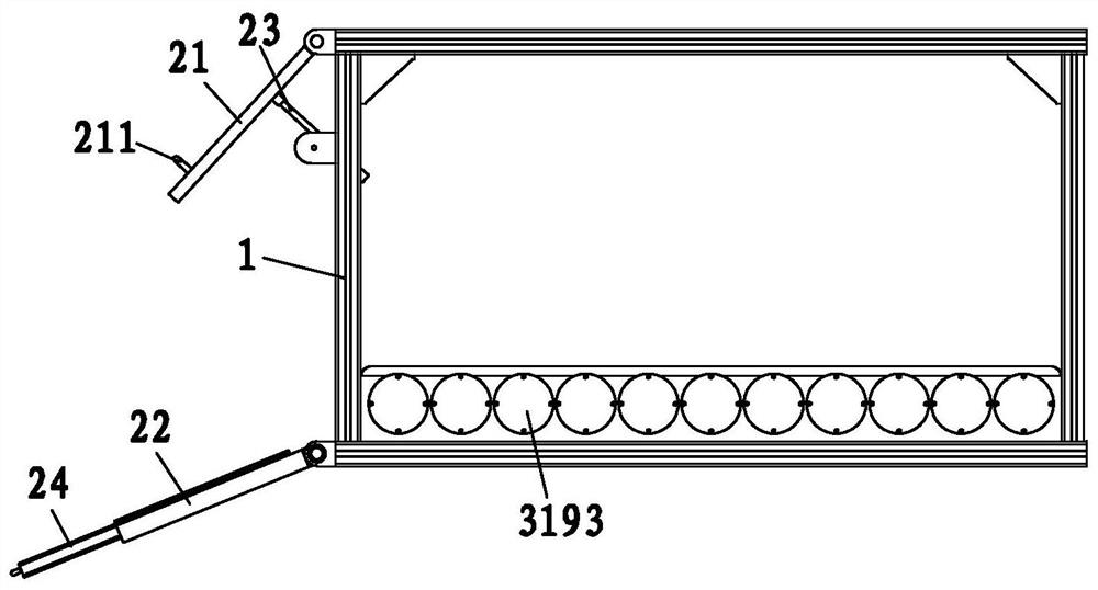
[0087] see Figure 1 to Figure 8 As shown, a kind of express delivery auxiliary unloading device of the present invention, comprises the compartment body 1 with rear compartment door 2, the goods transmission mechanism 3 that is located at the inner bottom of compartment body 1 and the driving mechanism 4 that drives goods transmission mechanism 3 to convey; The cargo transmission mechanism 3 includes two or more roller axes 31 that rotate at the inner bottom of the compartment body 1;
[0088] Except for the first roller axis 31, the front end of each roller axis 31 is provided with a first sprocket 311; except for the last roller axis 31, the rear end of each roller axis 31 is provided with a second chain wheel 312; the first sprockets 311 of the drum axis 31 are in groups of two, and the first sprockets 311 of the same group are connected through the first roller chain 313; the second sprockets 312 of the drum axis 31 are in two Two are a group, and the second sprockets 31...
specific Embodiment 2
[0118] see Figure 1 to Figure 15 As shown, the present invention is an express auxiliary unloading device. The difference from the first embodiment is that in the second embodiment, the rear compartment door 2 includes an upper door panel 21 and a lower door panel 22, and the top of the upper door panel 21 is The rotation pivot is connected above the unloading outlet of the carriage body 1 , and the bottom of the lower door panel 22 is pivotally connected below the discharge outlet of the carriage body 1 . By adopting the setting mode of the upper and lower doors, the lower door panel 22 can be opened for unloading during the specific unloading process, while the upper door panel 21 can block the goods above, thereby preventing the goods from falling directly.
[0119] In the present invention, in order to facilitate the delivery of goods and prevent larger goods from being blocked by the upper door panel 21 and cannot be delivered, a tensile support mechanism 23 is provided ...
specific Embodiment 3
[0135] see Figure 1 to Figure 18 As shown, the present invention is an express auxiliary unloading device. The difference from the second embodiment is that in the third embodiment, the drive mechanism 4 includes a first transmission wheel 41, a second transmission wheel 42, a swing lever 43 and Transmission strip 44;
[0136] The first transmission wheel 41 is fixedly sleeved on the roller axis 31. In practice, the first transmission wheel 41 can be fixedly sleeved on the last roller axis 31; Rotationally connected, the lower part extends downwards to the front end of the rear wheel 11 of the carriage body 1; the second transmission wheel 42 is rotationally connected to the lower part of the swing rod 43; one end of the transmission bar 44 is sleeved on the first transmission wheel 41 , and the other end is sheathed on the second transmission wheel 42; when the swing lever 43 is swung downward, the second transmission wheel 42 is abutted against the rear wheel 11 of the car...
PUM
 Abstract
Description
Claims
Application Information
 - R&D
- Intellectual Property
- Life Sciences
- Materials
- Tech Scout
- Unparalleled Data Quality
- Higher Quality Content
- 60% Fewer Hallucinations
Browse by: Latest US Patents, China's latest patents, Technical Efficacy Thesaurus, Application Domain, Technology Topic, Popular Technical Reports.
© 2025 PatSnap. All rights reserved.Legal|Privacy policy|Modern Slavery Act Transparency Statement|Sitemap|About US| Contact US: help@patsnap.com


