Eureka AIR delivers breakthrough ideas for toughest innovation challenges, trusted by R&D personnel around the world.

Convenient-to-disassemble anti-blocking drainage channel for agricultural water conservancy engineering

A technology of water conservancy projects and drainage channels, applied in agriculture, soil drainage, application, etc., can solve problems such as blockage, damage to the surrounding environment of residues and waste, inconvenient disassembly and assembly of concrete drainage channels, etc., and achieve the effect of convenient disassembly and assembly

Inactive Publication Date: 2020-09-29
刘小莉
View PDF6 Cites 0 Cited by
  • Summary
  • Abstract
  • Description
  • Claims
  • Application Information

AI Technical Summary

Problems solved by technology

[0004] The present invention proposes a detachable anti-blocking drainage channel for agricultural water conservancy projects, which is used to solve the problem that most of the existing drainage channels for agricultural water conservancy projects in the background technology are made of concrete pouring, which is easily affected by the damage in farmland or reservoirs. The blockage caused by the impact of debris, and the concrete drainage tank is not easy to disassemble and assemble, and the residue and waste left after dismantling will also bring great damage to the surrounding environment.

Method used


Image

  • Convenient-to-disassemble anti-blocking drainage channel for agricultural water conservancy engineering
  • Convenient-to-disassemble anti-blocking drainage channel for agricultural water conservancy engineering
  • Convenient-to-disassemble anti-blocking drainage channel for agricultural water conservancy engineering

Examples


Embodiment Construction

[0024] In describing the present invention, it should be understood that the terms "upper", "lower", "front", "rear", "left", "right", "top", "bottom", "inner", " The orientation or positional relationship indicated by "outside", etc. is based on the orientation or positional relationship shown in the drawings, and is only for the convenience of describing the present invention and simplifying the description, rather than indicating or implying that the referred device or element must have a specific orientation, so as to Specific orientation configurations and operations, therefore, are not to be construed as limitations on the invention.

[0025] The following will clearly and completely describe the technical solutions in the embodiments of the present invention with reference to the accompanying drawings in the embodiments of the present invention. Obviously, the described embodiments are only some, not all, embodiments of the present invention.

[0026] refer to Figure ...


PUM


Abstract

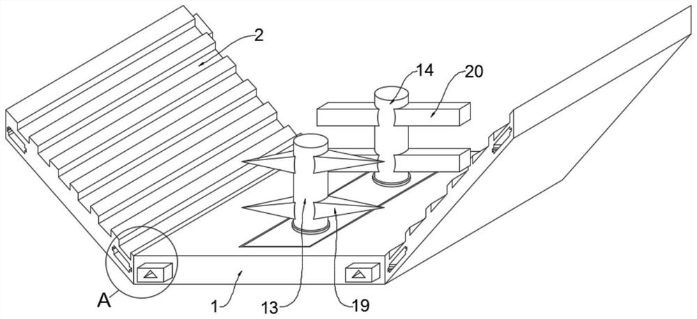
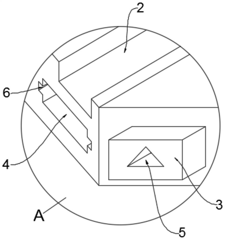
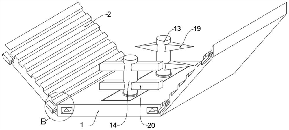
The invention discloses a convenient-to-disassemble anti-blocking drainage channel for agricultural water conservancy engineering. The drainage channel comprises a drainage channel body, a limiting mechanism is arranged on the side wall of the front end of the drainage channel body, and a clamping mechanism is arranged on the side wall of the rear end of the drainage channel body. According to thedrainage channel, limiting blocks and connecting blocks on the drainage channel body are respectively inserted into rectangular grooves and limiting grooves of an adjacent drainage channel body, so that a conical columnar clamping block in each rectangular groove is inserted into a conical columnar clamping groove in the corresponding limiting block, and rectangular protrusions on the connectingblocks are inserted into rectangular insertion grooves in the limiting grooves. The adjacent drainage channel bodies are effectively fixed, and meanwhile disassembly is convenient to achieve. Multiplestirring plates on a second rotating rod are pushed by waterflow to rotate to drive a chain drum on the second rotating rod to rotate, so that the chain drum is rotationally matched with a transmission chain to drive multiple conical cutters on a first rotating rod to rotate, cutting cleaning of sundries in the drainage channel bodies is achieved, and the drainage channel bodies are prevented from blocking.

Description

technical field [0001] The invention relates to the technical field of drainage tanks, in particular to a detachable anti-blocking drainage tank for agricultural water conservancy projects. Background technique [0002] The drainage tank is a facility used to adjust the water distribution in the farmland. On the one hand, it is to prevent excessive rainwater from affecting the normal growth of crops. On the other hand, it is used to discharge the water source in the reservoir into the farmland to improve the water conservancy of the farmland. During construction, drainage channels are widely used. [0003] Most of the existing drainage channels for agricultural water conservancy projects are made of concrete, which is easily blocked by the debris in the farmland or the reservoir, and the concrete drainage channels are not easy to disassemble. It will also cause great damage to the surrounding environment. Now a kind of agricultural water conservancy project is proposed to s...

Claims


Application Information

Patent Timeline
Patent Type & Authority Applications(China)
IPC IPC(8): E03F3/04E02B11/00
CPCE02B11/00E02B11/005E03F3/04
Inventor 刘小莉黄艳
Owner 刘小莉
Why Eureka
Eureka Blog
Learn More