
Interior wall template and wall surface template assembling body

A formwork group and formwork technology, which is applied in the direction of formwork/formwork/work frame, connectors of formwork/formwork/work frame, and preparation of building components on site, which can solve the problem of increasing construction costs and consuming time for assembly and disassembly , Reduce the efficiency of assembly and disassembly, etc.

Pending Publication Date: 2020-09-29
SNTO TECH GRP
View PDF0 Cites 1 Cited by
  • Summary
  • Abstract
  • Description
  • Claims
  • Application Information

AI Technical Summary

Problems solved by technology

[0002] With the popularization of aluminum formwork in the field of construction, efficient assembly and disassembly has always been one of the development trends of aluminum formwork. Standardized design of aluminum formwork is an effective way to achieve efficient assembly and disassembly. However, standardized design is not suitable for all formwork installations. Disassembly can achieve the purpose of high efficiency
[0003] In the prior art, when installing the formwork on the inner side of the wall, it is necessary to detachably install an elevated angle aluminum on the end of the standard formwork close to the ground, so that subsequent workers can remove the standard formwork and apply the standard formwork to other buildings. However, the installation of high angle aluminum consumes time for assembly and disassembly, seriously reduces the efficiency of assembly and disassembly, and increases construction costs

Method used


Image

  • Interior wall template and wall surface template assembling body
  • Interior wall template and wall surface template assembling body
  • Interior wall template and wall surface template assembling body

Examples


Embodiment Construction

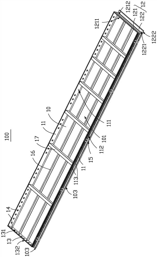
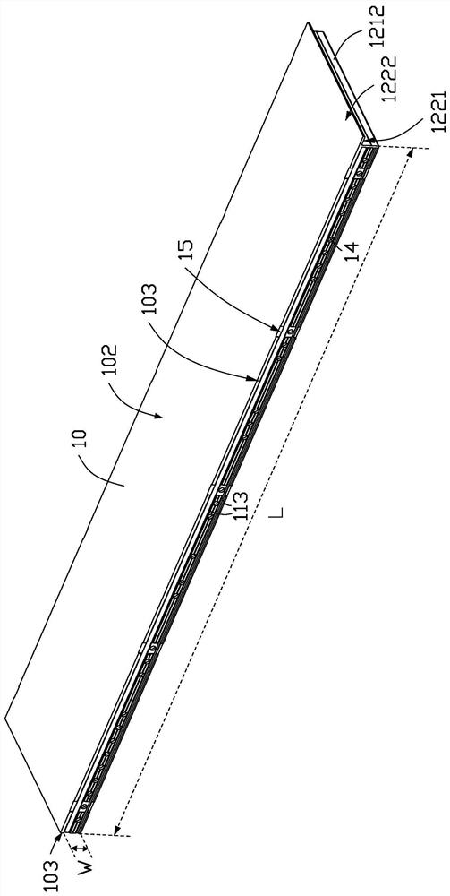
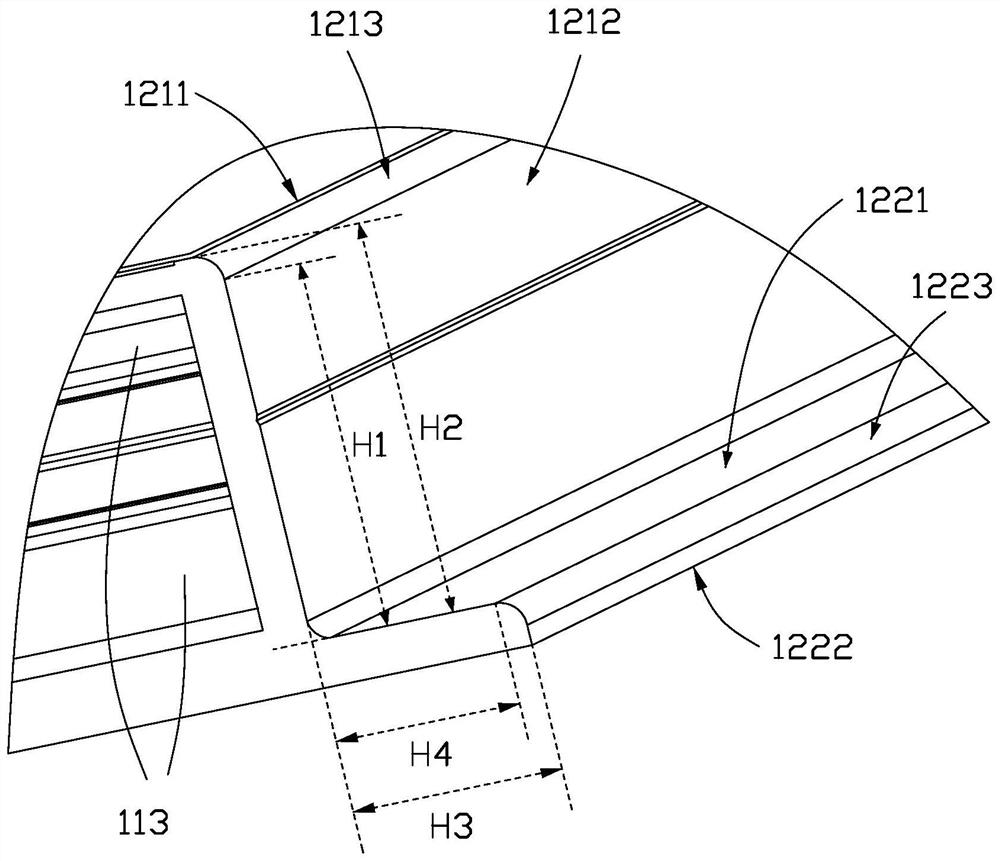
[0043] The following will be attached in conjunction with specific examples Figure 1-4 The technical solution of the present invention is clearly and completely described. Apparently, the described embodiments are only some, not all, embodiments of the present invention. Based on the implementation manners in the present invention, all other implementation manners obtained by persons of ordinary skill in the art without making creative efforts belong to the scope of protection of the present invention. Unless otherwise defined, all technical and scientific terms used herein have the same meaning as commonly understood by one of ordinary skill in the technical field of the invention. The terms used herein in the description of the present invention are for the purpose of describing specific embodiments only, and are not intended to limit the present invention.

[0044] See figure 1 and figure 2 , the present invention provides an interior wall template 100, the interior w...


PUM


Abstract

The invention provides an interior wall template. The interior wall template comprises a main body part, two side connecting plates, a first end connecting plate and a second end connecting plate; oneside connecting plate, the first end connecting plate, the other side connecting plate and the second end connecting plate are end to end in sequence to be surrounded at the edge of one side of the main body part; the first end connecting plate comprises an end sealing plate and a raising plate which is detachably connected to the end sealing plate; the two ends of the end sealing plate are respectively connected between the two side connecting plates; the raising plate extends in the direction far away from the main body part; and by detachably connecting the end sealing plate with the raising plate, the time waste caused by assembling and disassembling raising angle aluminum is avoided, and the assembling and disassembling efficiency is enhanced. In addition, the invention further provides a wall surface template assembling body.

Description

technical field [0001] The invention relates to an interior wall formwork and a wall surface formwork assembly. Background technique [0002] With the popularization of aluminum formwork in the field of construction, efficient assembly and disassembly has always been one of the development trends of aluminum formwork. Standardized design of aluminum formwork is an effective way to achieve efficient assembly and disassembly. However, standardized design is not suitable for all formwork installations. Demolition can achieve the purpose of high efficiency. [0003] In the prior art, when the formwork on the inside of the wall is installed, it is necessary to detachably install an elevated angle aluminum on the end of the standard formwork close to the ground, so that subsequent workers can remove the standard formwork and apply the standard formwork to other buildings. position, however, the installation of high angle aluminum consumes time for assembly and disassembly, seriou...

Claims


Application Information

Patent Timeline
Patent Type & Authority Applications(China)
IPC IPC(8): E04G11/08E04G17/00E04G17/075E04G17/14
CPCE04G11/08E04G17/00E04G17/075E04G17/14E04G11/085
Inventor 彭福龙李坚曾政鲁纯
Owner SNTO TECH GRP
Learn More