
Raman spectrometer capable of automatically discriminating sample and method for automatically discriminating sample

A Raman spectrometer and sample technology, applied in the field of Raman spectroscopy, can solve the problems of long Raman detection time, double working time, weak Raman signal, etc., and achieve small structural space requirements, reduced detection time, and low cost Effect

Pending Publication Date: 2020-07-14
奥谱天成(厦门)光电有限公司
View PDF0 Cites 0 Cited by
  • Summary
  • Abstract
  • Description
  • Claims
  • Application Information

AI Technical Summary

Problems solved by technology

[0003] At present, high-throughput Raman spectrometers based on Raman spectroscopy are all manual detection. Since the Raman signal is very weak, the signal intensity can only be enhanced by prolonging the integration time; To scan the dark current, the actual working time is doubled, so the Raman detection time is relatively long, and the detection time of a sample generally needs to reach 20-40s. The 1064nm Raman signal is weaker, and the detection time is longer. The detection of a single sample for several minutes
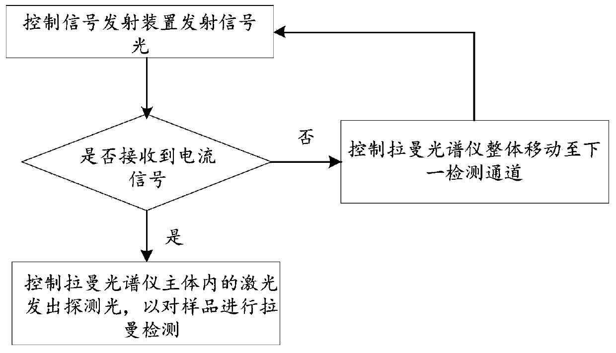
[0004] In the automatic detection process, the samples are placed on the sample plate, and the Raman spectrometer detects each sample through sequential detection. However, if no sample is placed at a certain position on the sample plate, the problem of empty detection may occur. lead to a lot of wasted time

Method used


Image

  • Raman spectrometer capable of automatically discriminating sample and method for automatically discriminating sample
  • Raman spectrometer capable of automatically discriminating sample and method for automatically discriminating sample
  • Raman spectrometer capable of automatically discriminating sample and method for automatically discriminating sample

Examples


Embodiment Construction

[0023] The following will clearly and completely describe the technical solutions in the embodiments of the present invention with reference to the accompanying drawings in the embodiments of the present invention. Obviously, the described embodiments are only some, not all, embodiments of the present invention. Based on the embodiments of the present invention, all other embodiments obtained by persons of ordinary skill in the art without creative efforts fall within the protection scope of the present invention.

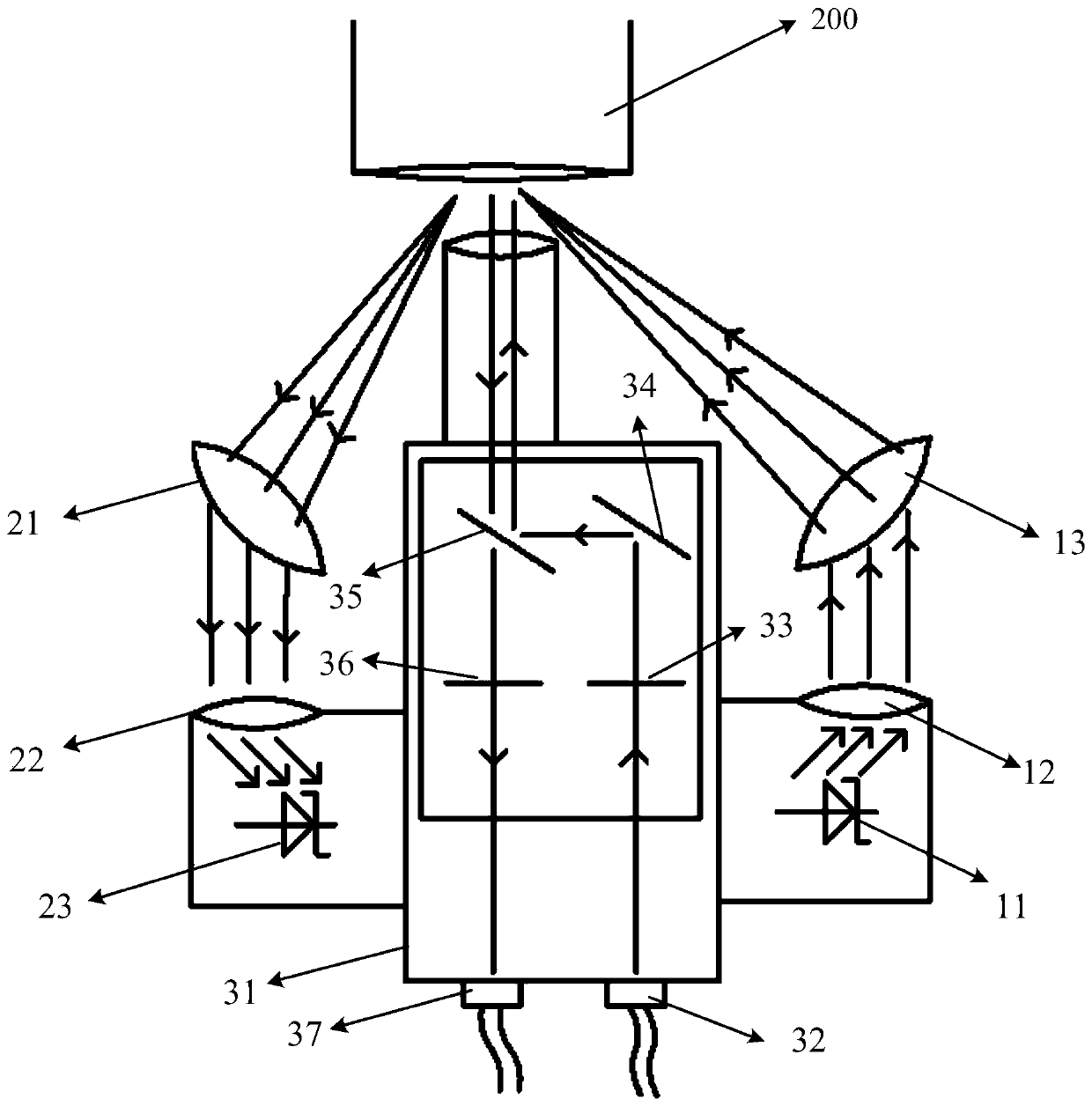
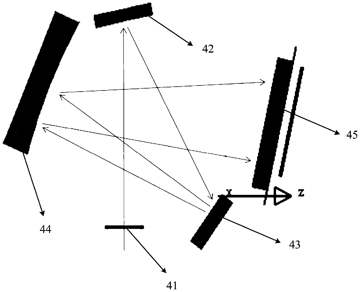
[0024] see figure 1 and figure 2 , the first embodiment of the present invention provides a Raman spectrometer for automatically identifying samples, including a Raman spectrometer main body, a detection probe connected to the Raman spectrometer main body, and signal signals arranged on both sides of the Raman spectrometer probe. Transmitter and signal receiver. Wherein, the signal light emitted by the signal emitting device faces the detection direction of the ...


PUM


Abstract

The invention discloses a Raman spectrometer capable of automatically discriminating a sample and a method for automatically discriminating a sample. The Raman spectrometer comprises a Raman spectrometer main body, a detection probe, and a signal transmitting device and a signal receiving device which are arranged on two sides of the Raman spectrometer probe, wherein signal light emitted by the signal transmitting device faces the detection direction of the detection probe and is configured to be received by the signal receiving device after being reflected by a sample correspondingly detectedby the detection probe. According to the embodiment, before Raman detection, whether the sample exists on the detection channel or not is judged through the signal transmitting device and the signalreceiving device, and subsequent Raman detection is carried out only when the sample exists, so that time consumption caused by empty detection due to the fact that no sample exists in the detection channel is avoided. Besides, the infrared photoelectric sensor is used for automatically detecting whether a sample exists or not, compared with a camera, the detection time is greatly shortened, the requirement for structural space is small, installation is easy, and cost is low.

Description

technical field [0001] The invention relates to the field of Raman spectroscopy, in particular to a Raman spectrometer for automatically identifying samples and a method for automatically identifying samples. Background technique [0002] Raman spectrum is a kind of scattering spectrum. Raman spectroscopy is based on the Raman scattering effect discovered by Indian scientist C.V. Raman (Raman). It analyzes the scattering spectrum different from the frequency of the incident light to obtain molecular vibration and rotation information, and is applied to the study of molecular structure. a method of analysis. [0003] At present, high-throughput Raman spectrometers based on Raman spectroscopy are all manual detection. Since the Raman signal is very weak, the signal intensity can only be enhanced by prolonging the integration time; To scan the dark current, the actual working time is doubled, so the Raman detection time is relatively long, and the detection time of a sample g...

Claims


Application Information

Patent Timeline
IPC IPC(8): G01N21/65G01N21/01G01V8/12
CPCG01N21/01G01N21/65G01N2021/0112G01V8/12
Inventor 刘鸿飞刘罡洪鹏林
Owner 奥谱天成(厦门)光电有限公司
Learn More